
Safety Warning
DIY auto repair can cause serious injury, fire, or vehicle damage. These guides are for informational purposes only. Always follow OEM torque specs, wear PPE, and consult a certified mechanic if you are unsure. You are solely responsible for your safety.
2009 Hummer H3 L5-3.7LFACTORY OEM SERVICE PROCEDURE
Fuel Tank Module Replacement
Fuel Tank Module Replacement
Special Tools
J 45722 Fuel Sender Lock Ring Wrench
Removal Procedure
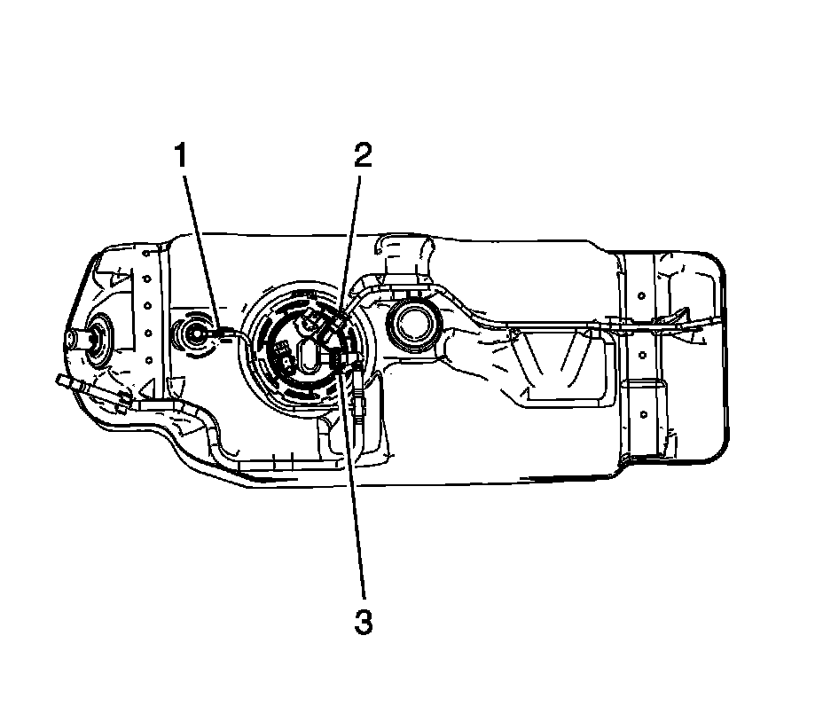
Caution: Clean all of the following areas before performing any disconnections in order to avoid possible contamination in the system:
* The fuel pipe connections
* The hose connections
* The areas surrounding the connections
1. Remove the fuel tank. Refer to Fuel Tank Replacement (Removal and Replacement).
2. Using a flare nut wrench and a back up wrench, disconnect the fuel feed line (2) fitting from the fuel tank module.
3. Disconnect the EVAP vapor line (1) from the fuel tank vent valve.
4. Disconnect the EVAP vapor line (3) quick connect from the fuel tank module. Refer to Plastic Collar Quick Connect Fitting Service (Plastic Collar Quick Connect Fitting Service).
5. Reposition the fuel feed and EVAP lines in order to access the lock ring.
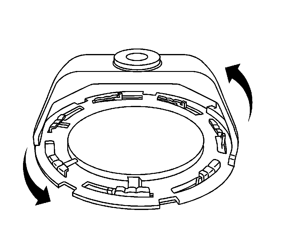
Caution: Avoid damaging the lock ring. Use only J-45722 to prevent damage to the lock ring.
Caution: Do Not handle the fuel sender assembly by the fuel pipes. The amount of leverage generated by handling the fuel pipes could damage the joints.
Note: Do NOT use impact tools. Significant force will be required to release the lock ring. The use of a hammer and screwdriver is not recommended. Secure the fuel tank in order to prevent fuel tank rotation.
6. Use the J 45722 and a long breaker-bar in order to unlock the fuel sender lock ring. Turn the J 45722 fuel sender lock ring in a counterclockwise direction.
7. Remove the cam lock ring from the fuel tank.
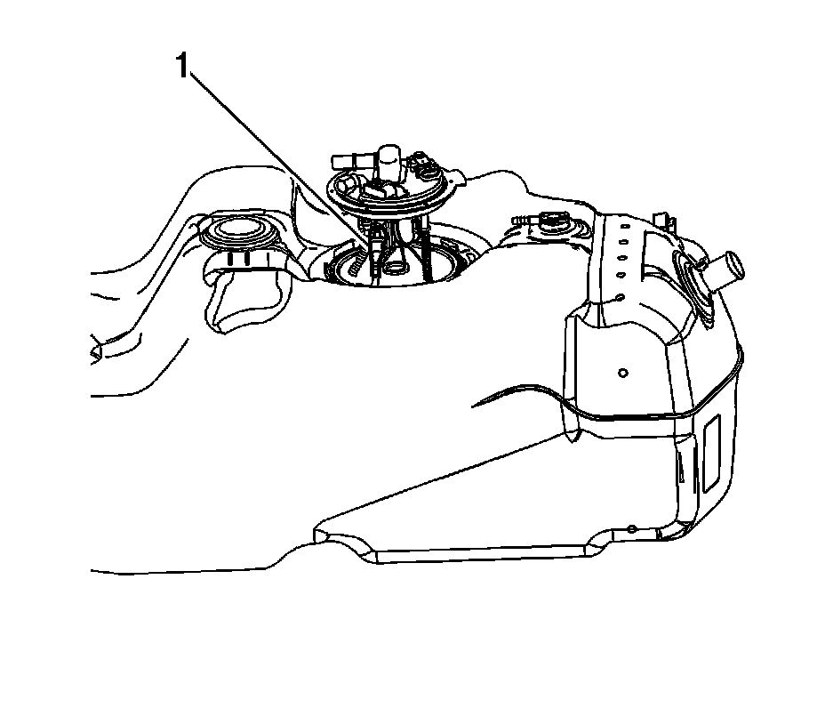
8. Raise the fuel tank module upward far enough to access the vapor line quick connect under the module cover.
9. Disconnect the vapor line quick connect (1) from the fuel tank module. Refer Plastic Collar Quick Connect Fitting Service (Plastic Collar Quick Connect Fitting Service).
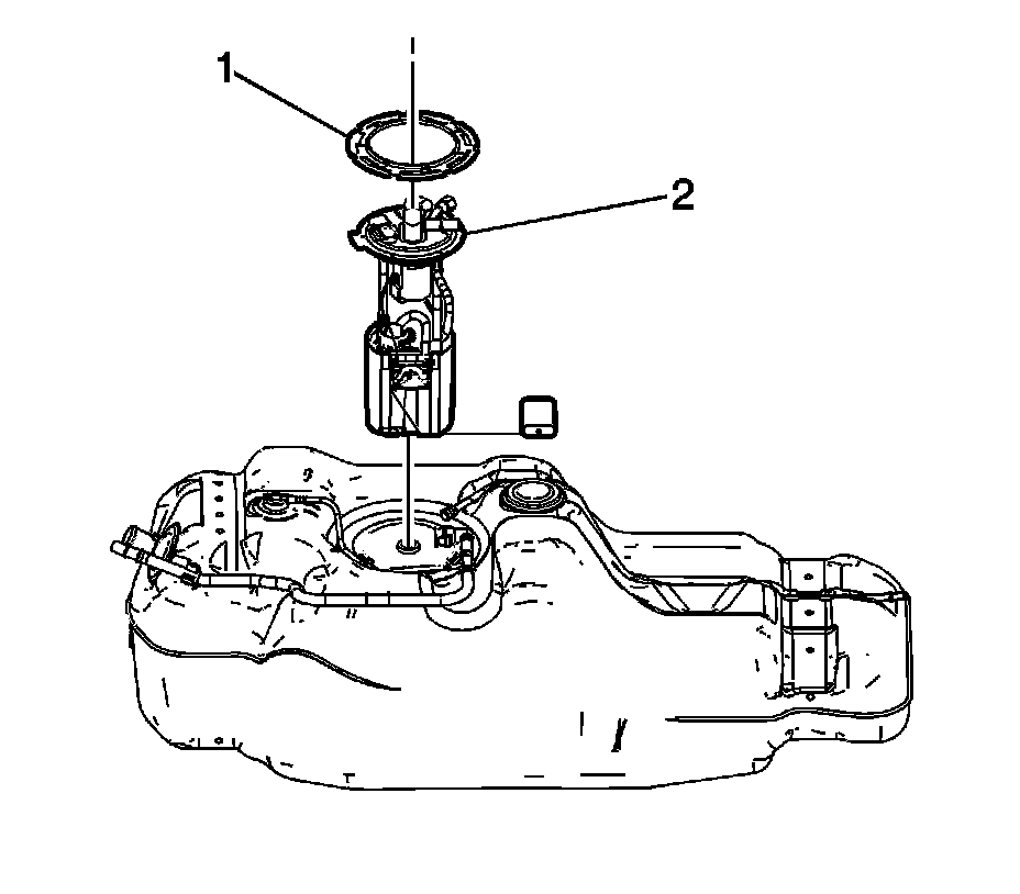
10. Tilt the module (2), to allow the fuel level sensor arm and float to clear the fuel tank module opening.
11. Remove the fuel tank module from the fuel tank.
12. Remove the fuel tank module seal. Do not reuse the seal.
Warning
Drain the fuel from the fuel sender assembly into an approved container in order to reduce the risk of fire and personal injury. Never store the fuel in an open container
13. Clean the fuel module sealing surfaces.
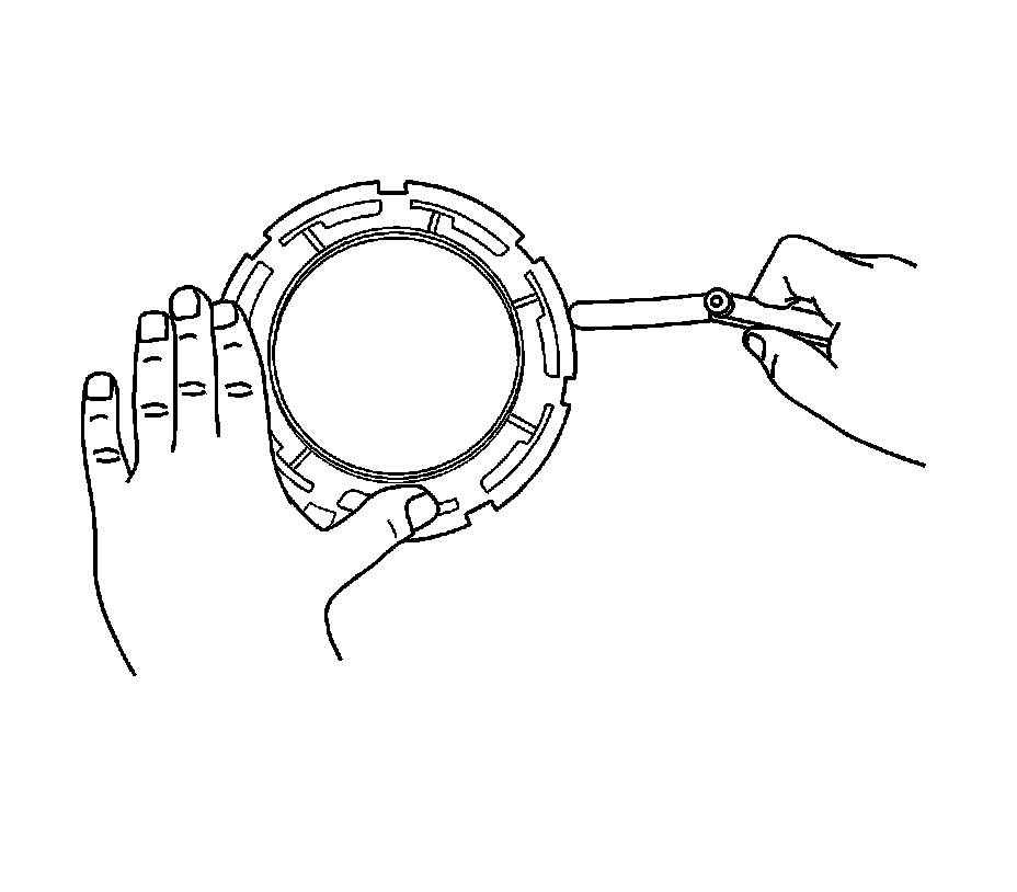
Note:
* Some lock ring were manufactured with DO NOT REUSE stamped into them. These lock rings may be reused if they are not damaged or warped.
* Inspect the lock ring for damage due to improper removal or installation procedures. If damage is found, install a NEW lock ring.
* Check the lock ring for flatness.
14. Place the lock ring on a flat surface. Measure the clearance between to lock ring and the flat surface using a feeler gage at 7 points.
15. If the warpage is less than 0.41 mm (0.016 in), the lock ring does not require replacement.
16. If the warpage is greater than 0.41 mm (0.016 in), the lock ring must be replaced.
Installation Procedure
1. Clean any contamination from the male pipe ends of the fuel tank module.
Warning
In order to reduce the risk of fire and personal injury that may result from a fuel leak, always replace the fuel sender gasket when reinstalling the fuel sender assembly.
2. Place the new fuel tank module seal on the fuel tank.
3. Insert the module (2) into the fuel tank allowing the fuel level sensor arm and float to clear module opening.
4. Lower the module (2) downward into the fuel tank.
5. Connect the vapor line quick connect (1) to the fuel tank module. Refer Plastic Collar Quick Connect Fitting Service (Plastic Collar Quick Connect Fitting Service).
6. Press the fuel tank module downward, aligning the locator tang with the locator notch in the fuel tank.
7. Position the cam lock ring to the fuel tank
Note: Always replace the fuel sender seal when installing the fuel sender assembly. Replace the lock ring if necessary. Do not apply any type of lubrication in the seal groove.
Ensure the lock ring is installed with the correct side facing upward. A correctly installed lock ring will only turn in a clockwise direction.
8. Use the J 45722 in order to install the fuel sender lock ring. Turn the fuel sender lock ring in a clockwise direction.
9. Position the fuel feed and EVAP lines to the module.
10. Connect the EVAP vapor line (1) to the fuel tank vent valve.
11. Connect the EVAP vapor line (3) quick connect to the fuel tank module. Refer to Plastic Collar Quick Connect Fitting Service (Plastic Collar Quick Connect Fitting Service).
Caution: Refer to Fastener Caution (Fastener Caution).
12. Using a flare nut wrench and a back up wrench, connect the fuel feed line (2) fitting to the fuel tank module.
Tighten the fitting to 30 Nm (22 lb ft).
13. Install the fuel tank. Refer to Fuel Tank Replacement (Removal and Replacement).
Factory Service Tools
Use the Manual With the Right Hardware
Pair factory procedures with proven DIY tools so the instructions are easier to execute.
Disclosure: Verified tool recommendations may earn an affiliate commission at no cost to you.
When to See a Mechanic
Stop DIY work and contact a certified mechanic immediately if any of the following apply:
- • You smell fuel, burning insulation, or see smoke.
- • Brakes feel soft, pull hard to one side, or make grinding noises.
- • The engine overheats, stalls repeatedly, or misfires under load.
- • You are missing required tools, torque specs, or safe lifting equipment.
- • You are not confident in the next step or safety outcome.
Rather have a pro handle this?
A certified mobile mechanic comes to your home or office. They bring the tools, you stay comfortable. No tow truck, no waiting room, no surprises.
Comes to youSame-day available12-month warranty
Get a Free QuoteNo obligation. See pricing before you book.