
Safety Warning
DIY auto repair can cause serious injury, fire, or vehicle damage. These guides are for informational purposes only. Always follow OEM torque specs, wear PPE, and consult a certified mechanic if you are unsure. You are solely responsible for your safety.
2005 Hummer H2 V8-6.0LFACTORY OEM SERVICE PROCEDURE
Engine Control Module: Service and Repair
POWERTRAIN CONTROL MODULE (PCM) REPLACEMENT
Service of the powertrain control module (PCM) should normally consist of either replacement of the PCM or electrically erasable programmable read only memory (EEPROM) programming. If the diagnostic procedures call for the PCM to be replaced, the PCM should be inspected first to see if the correct part is being used. If the correct part is being used, remove the faulty PCM and install the new service PCM.
- Remove any debris from the PCM connector surfaces before servicing the PCM. Inspect the PCM module connector gaskets when diagnosing or replacing the PCM. Ensure that the gaskets are installed correctly. The gaskets prevent contaminant intrusion into the PCM.
IMPORTANT: To prevent internal PCM damage, the ignition must be OFF when disconnecting or reconnecting power to the PCM. For example, when working with a battery cable, PCM pigtail, PCM fuse, or jumper cables.
- The replacement PCM must be programmed.
Removal Procedure
1. Using a scan tool, retrieve the percentage of remaining engine oil. Record the remaining engine oil life.
IMPORTANT: It is necessary to record the remaining engine oil life. If the replacement module is not programed with the remaining engine oil life, the engine oil life will default to 100 percent. If the replacement module is not programmed with the remaining engine oil life, the engine oil will need to be changed at 5,000 km (3,000 mi) from the last engine oil change.
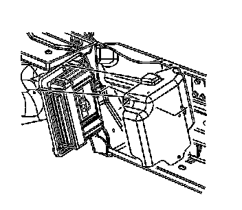
2. Release the PCM cover mounting holes away from the mounting tabs on the PCM mounting bracket.
3. Release the PCM cover from the mounting bracket.
4. Remove the PCM cover.
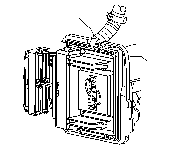
5. Loosen both PCM connector retaining bolts.
NOTE:
- Refer to PCM and ESD Notice in Service Precautions.
- In order to prevent internal damage to the PCM, the ignition must be OFF when disconnecting or reconnecting the PCM connector.
6. Disconnect the PCM harness connectors.
7. Release the spring latch from the PCM.
8. Release the PCM mounting tabs from the PCM.
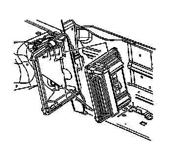
9. Remove the PCM from the engine compartment.
Installation Procedure
1. Install the PCM to the PCM mounting bracket ensuring that the mounting tabs are engaged.
2. Secure the spring latch to the PCM.
3. Connect the PCM connectors to the PCM.
NOTE: Refer to Fastener Notice in Service Precautions.
Tighten the PCM connector end fasteners to 8 N.m (71 lb in).
4. Install the PCM cover to the PCM mounting bracket, ensuring the mounting tabs on the PCM mounting bracket are engaged into the mounting holes in the PCM cover.
5. If a new PCM is being installed, program the PCM. Refer to Control Module References in Computer/Integrating Systems.
Factory Service Tools
Use the Manual With the Right Hardware
Pair factory procedures with proven DIY tools so the instructions are easier to execute.
Disclosure: Verified tool recommendations may earn an affiliate commission at no cost to you.
When to See a Mechanic
Stop DIY work and contact a certified mechanic immediately if any of the following apply:
- • You smell fuel, burning insulation, or see smoke.
- • Brakes feel soft, pull hard to one side, or make grinding noises.
- • The engine overheats, stalls repeatedly, or misfires under load.
- • You are missing required tools, torque specs, or safe lifting equipment.
- • You are not confident in the next step or safety outcome.
Rather have a pro handle this?
A certified mobile mechanic comes to your home or office. They bring the tools, you stay comfortable. No tow truck, no waiting room, no surprises.
Comes to youSame-day available12-month warranty
Get a Free QuoteNo obligation. See pricing before you book.