
Safety Warning
DIY auto repair can cause serious injury, fire, or vehicle damage. These guides are for informational purposes only. Always follow OEM torque specs, wear PPE, and consult a certified mechanic if you are unsure. You are solely responsible for your safety.
2010 Honda Element 4WD L4-2.4LFACTORY OEM SERVICE PROCEDURE
Ignition System: Testing and Inspection
Ignition Coil Relay Circuit Troubleshooting
1. Check the No. 16 (15 A) fuse in the under-dash fuse/ relay box.
Is the fuse OK?
YES -
Reinstall the fuse, then go to step 2.
NO -
Replace the fuse. If the fuse continues to blow, locate and repair the short in the circuit between the under-dash fuse/relay box and the ignition coil relay.�
2. Remove the ignition coil relay, and test it Testing and Inspection.
Is the relay OK?
YES -
Go to step 3.
NO -
Replace the ignition coil relay.�
3. Measure the voltage between body ground and ignition coil relay 4P socket terminal No. 2 and No. 4 individually.
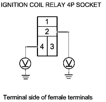
Is there battery voltage?
YES -
Go to step 4.
NO -
Repair an open in the wire between under-dash fuse/relay box and ignition coil relay.�
4. Check for continuity between ignition coil relay 4P socket terminal No. 1 and each ignition coil 3P connector terminal No. 3.
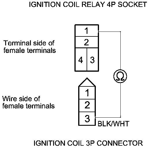
Is there continuity?
YES -
Go to step 5.
NO -
Repair an open in the wire between ignition coil relay 4P socket terminal No. 1 and ignition coil 3P connector terminal No. 3.�
5. Check for continuity between each ignition coil 3P connector terminal No. 2 and body ground.
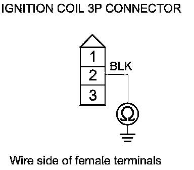
Is there continuity?
YES -
Go to step 6.
NO -
Repair an open in the wire between ignition coil 3P connector terminal No. 2 and body ground G102.�
6. Connect the HDS to the DLC.
7. Turn the ignition switch to ON (II).
8. Make sure the HDS communicates with the vehicle and the ECM/PCM. If it does not communicate, troubleshoot the DLC circuit Testing and Inspection.
9. Jump the SCS line with the HDS, then turn the ignition switch to LOCK (0).
NOTE: This step must be done to protect the ECM/ PCM from damage.
10. Disconnect ECM/PCM connector E (31P).
11. Check for continuity between ignition coil relay 4P socket terminal No. 3 and body ground.
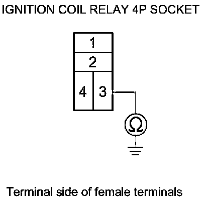
Is there continuity?
YES -
Repair a short in the wire between ignition coil relay 4P socket terminal No. 3 and ECM/PCM connector terminal E7.�
NO -
Go to step 12.
12. Check for continuity between ignition coil relay 4P socket terminal No. 3 and ECM/PCM connector terminal E7.

Is there continuity?
YES -
The system is OK at this time. Check for loose or poor connections at the ignition coil relay and ECM/PCM connector terminal E7.�
NO -
Repair an open in the wire between ignition coil relay 4P socket terminal No. 3 and ECM/PCM connector terminal E7.�
Factory Service Tools
Use the Manual With the Right Hardware
Pair factory procedures with proven DIY tools so the instructions are easier to execute.
Disclosure: Verified tool recommendations may earn an affiliate commission at no cost to you.
When to See a Mechanic
Stop DIY work and contact a certified mechanic immediately if any of the following apply:
- • You smell fuel, burning insulation, or see smoke.
- • Brakes feel soft, pull hard to one side, or make grinding noises.
- • The engine overheats, stalls repeatedly, or misfires under load.
- • You are missing required tools, torque specs, or safe lifting equipment.
- • You are not confident in the next step or safety outcome.