
Safety Warning
DIY auto repair can cause serious injury, fire, or vehicle damage. These guides are for informational purposes only. Always follow OEM torque specs, wear PPE, and consult a certified mechanic if you are unsure. You are solely responsible for your safety.
2004 Honda S2000 L4-2.2LFACTORY OEM SERVICE PROCEDURE
Troubleshooting Tests
Testing for Voltage
When testing for voltage at a connector without wire seals, you do not have to separate the two halves of the connector. Instead, probe the connector from the back. Always check both sides of the connector because dirty, corroded, and bent terminals can cause problems (no electrical contact = an open).
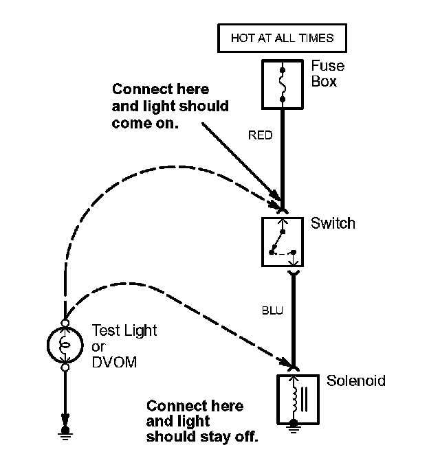
1. Connect one lead of the test light to a known good ground, or, if you're using a digital volt ohmmeter (DVOM), place it in the appropriate DC volts range, and connect its negative lead to ground.
2. Connect the other lead of the test light or DVOM to the point you want to check.
3. If the test light glows, there is voltage present. If you're using a DVOM, note the voltage reading. It should be within one volt of measured battery voltage. A loss of more than one volt indicates a problem.
NOTE: Always use a DVOM on high impedance circuits. A test light may not glow (even with battery voltage present).
Testing for Continuity
When testing for continuity at a connector without wire seals, you do not have to separate the two halves of the connector. Instead, probe the connector from the back. Always check both sides of the connector because dirty, corroded, and bent terminals can cause problems (no electrical contact = an open).
1. Disconnect the negative cable from the car battery. If you're using a DVOM, place it in the lowest OHMS" range.
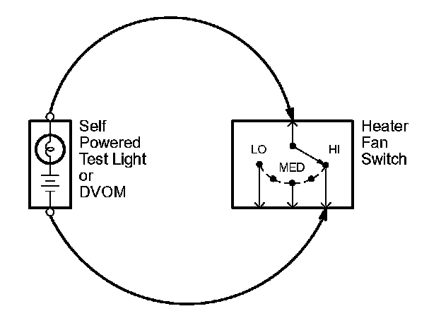
2. Connect one lead of a self-powered test light or DVOM to one end of the part of the circuit you want to test.
3. Connect the other lead to the other end.
4. If the self-powered test light glows, there is continuity. If you're using a DVOM, a low reading or no reading (zero), means good continuity.
Testing for Voltage Drop
Wires, connectors, and switches are designed to conduct current with a minimum loss of voltage. A voltage drop of more than one volt indicates a problem.
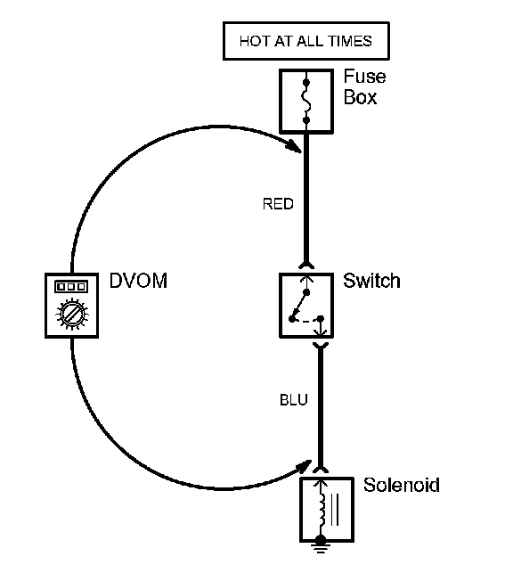
1. Place the digital volt/ohmmeter (DVOM) in the appropriate DC volts range. Connect the positive lead to the end of the wire (or to the connector or switch) closest to the battery.
2. Connect the negative lead to the other end of the wire (or the other side of the connector or switch).
3. Turn on the components in the circuit.
4. The DVOM will show the difference in voltage between the two points. A difference, or drop, of more than one volt indicates a problem. Check the circuit for loose, dirty, or bent terminals.
Testing for a Short with a Test Light or DVOM
1. Remove the blown fuse and disconnect the load.
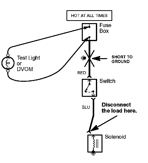
2. Connect a test light or digital volt/ohmmeter (DVOM), switched to the appropriate DC volts range, across the fuse terminals to make sure voltage is present. You might have to turn the ignition switch to ON; check the schematic to see.
3. Beginning near the fuse box, wiggle the harness. Continue this at convenient points about six inches apart while watching the test light or DVOM.
4. Where the test light goes off, or the DVOM voltage drops to zero, there is a short to ground in the wiring near that point.
NOTE: Always use a DVOM on high impedance circuits. A test light may not glow (even with battery voltage present).
Testing for a Short with a Self-Powered Test Light or DVOM
1. Remove the blown fuse and disconnect the battery and load.
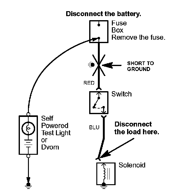
2. Connect one lead of a self-powered test light or digital volt/ohmmeter (DVOM) (switched to the lowest "OHMS" range) to the fuse terminal on the load side.
3. Connect the other lead to a known good ground.
4. Beginning near the fuse box, wiggle the harness. Continue this at convenient points about six inches apart while watching the test light or DVOM.
5. If the self-powered test light goes on or the DVOM displays a low reading or no reading (zero), there is a short to ground in the wiring near that point.
Testing for a Short with a Short Circuit Locator (Short Finder)
1. Remove the blown fuse. Leave the battery connected.
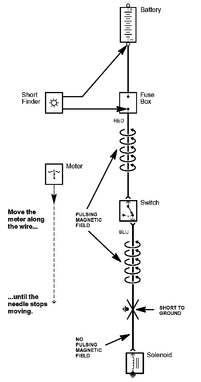
2. Connect the short finder across the battery terminals and the load (component) side of the fuse terminal.
3. Close all switches in the circuit you're testing.
4. Turn on the short finder. This creates a pulsing magnetic field around the wiring between the fuse box and the short.
5. Beginning at the fuse box, slowly move the short finder along the circuit wiring. The meter will read current pulses through sheet metal and body trim. As long as the meter is between the fuse and the short, the needle will move with each current pulse. Once you move the meter past the point of the short, the needle will stop moving. Check the wiring and connectors in this area to locate the cause of the short.
When testing for voltage at a connector without wire seals, you do not have to separate the two halves of the connector. Instead, probe the connector from the back. Always check both sides of the connector because dirty, corroded, and bent terminals can cause problems (no electrical contact = an open).
1. Connect one lead of the test light to a known good ground, or, if you're using a digital volt ohmmeter (DVOM), place it in the appropriate DC volts range, and connect its negative lead to ground.
2. Connect the other lead of the test light or DVOM to the point you want to check.
3. If the test light glows, there is voltage present. If you're using a DVOM, note the voltage reading. It should be within one volt of measured battery voltage. A loss of more than one volt indicates a problem.
NOTE: Always use a DVOM on high impedance circuits. A test light may not glow (even with battery voltage present).
Testing for Continuity
When testing for continuity at a connector without wire seals, you do not have to separate the two halves of the connector. Instead, probe the connector from the back. Always check both sides of the connector because dirty, corroded, and bent terminals can cause problems (no electrical contact = an open).
1. Disconnect the negative cable from the car battery. If you're using a DVOM, place it in the lowest OHMS" range.
2. Connect one lead of a self-powered test light or DVOM to one end of the part of the circuit you want to test.
3. Connect the other lead to the other end.
4. If the self-powered test light glows, there is continuity. If you're using a DVOM, a low reading or no reading (zero), means good continuity.
Testing for Voltage Drop
Wires, connectors, and switches are designed to conduct current with a minimum loss of voltage. A voltage drop of more than one volt indicates a problem.
1. Place the digital volt/ohmmeter (DVOM) in the appropriate DC volts range. Connect the positive lead to the end of the wire (or to the connector or switch) closest to the battery.
2. Connect the negative lead to the other end of the wire (or the other side of the connector or switch).
3. Turn on the components in the circuit.
4. The DVOM will show the difference in voltage between the two points. A difference, or drop, of more than one volt indicates a problem. Check the circuit for loose, dirty, or bent terminals.
Testing for a Short with a Test Light or DVOM
1. Remove the blown fuse and disconnect the load.
2. Connect a test light or digital volt/ohmmeter (DVOM), switched to the appropriate DC volts range, across the fuse terminals to make sure voltage is present. You might have to turn the ignition switch to ON; check the schematic to see.
3. Beginning near the fuse box, wiggle the harness. Continue this at convenient points about six inches apart while watching the test light or DVOM.
4. Where the test light goes off, or the DVOM voltage drops to zero, there is a short to ground in the wiring near that point.
NOTE: Always use a DVOM on high impedance circuits. A test light may not glow (even with battery voltage present).
Testing for a Short with a Self-Powered Test Light or DVOM
1. Remove the blown fuse and disconnect the battery and load.
2. Connect one lead of a self-powered test light or digital volt/ohmmeter (DVOM) (switched to the lowest "OHMS" range) to the fuse terminal on the load side.
3. Connect the other lead to a known good ground.
4. Beginning near the fuse box, wiggle the harness. Continue this at convenient points about six inches apart while watching the test light or DVOM.
5. If the self-powered test light goes on or the DVOM displays a low reading or no reading (zero), there is a short to ground in the wiring near that point.
Testing for a Short with a Short Circuit Locator (Short Finder)
1. Remove the blown fuse. Leave the battery connected.
2. Connect the short finder across the battery terminals and the load (component) side of the fuse terminal.
3. Close all switches in the circuit you're testing.
4. Turn on the short finder. This creates a pulsing magnetic field around the wiring between the fuse box and the short.
5. Beginning at the fuse box, slowly move the short finder along the circuit wiring. The meter will read current pulses through sheet metal and body trim. As long as the meter is between the fuse and the short, the needle will move with each current pulse. Once you move the meter past the point of the short, the needle will stop moving. Check the wiring and connectors in this area to locate the cause of the short.
Factory Service Tools
Use the Manual With the Right Hardware
Pair factory procedures with proven DIY tools so the instructions are easier to execute.
Disclosure: Verified tool recommendations may earn an affiliate commission at no cost to you.
When to See a Mechanic
Stop DIY work and contact a certified mechanic immediately if any of the following apply:
- • You smell fuel, burning insulation, or see smoke.
- • Brakes feel soft, pull hard to one side, or make grinding noises.
- • The engine overheats, stalls repeatedly, or misfires under load.
- • You are missing required tools, torque specs, or safe lifting equipment.
- • You are not confident in the next step or safety outcome.
Rather have a pro handle this?
A certified mobile mechanic comes to your home or office. They bring the tools, you stay comfortable. No tow truck, no waiting room, no surprises.
Comes to youSame-day available12-month warranty
Get a Free QuoteNo obligation. See pricing before you book.