
Safety Warning
DIY auto repair can cause serious injury, fire, or vehicle damage. These guides are for informational purposes only. Always follow OEM torque specs, wear PPE, and consult a certified mechanic if you are unsure. You are solely responsible for your safety.
2004 Honda S2000 L4-2.2LFACTORY OEM SERVICE PROCEDURE
Cylinder Head Installation
Cylinder Head Installation
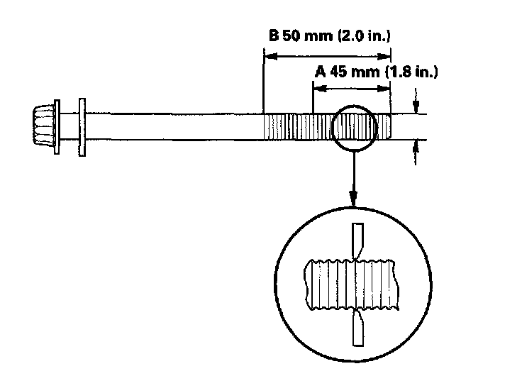
1. Measure the diameter of each cylinder head bolt at point A and point B. If either diameter is less than 11.5 mm (0.45 inch). replace the cylinder head bolt.
2. Clean the cylinder head and block surfaces.

3. Apply liquid gasket, part No. 08718-0009, to the shaded areas (A) of the cylinder head gasket mating surface of the block and chain case.
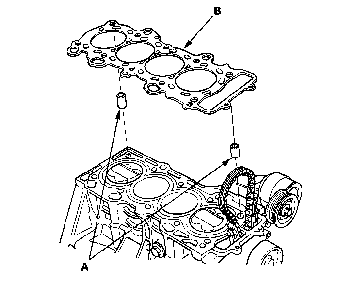
4. Install the dowel pins (A) and the new cylinder head gasket (B).

5. Apply liquid gasket, part No. 08718-0009, to the cylinder head mating surface of the block and chain case within 5 mm of the edge of the cylinder head Basket.
6. Install the cylinder head on the block.
7. Apply engine oil to the threads and under the heads of all the cylinder head bolts.
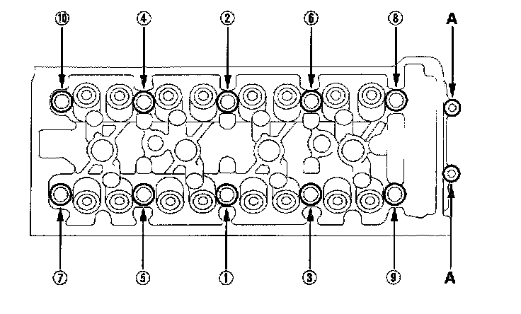
8. Tighten the cylinder head bolts in sequence to 29 Nm (3.0 kgf-m, 22 ft. lbs.). Use a beam-type torque wrench. When using a preset-type torque wrench, be sure to tighten slowly and do not overtighten. If a bolt makes any noise while you are torquing it, loosen the bolt an retighten it.
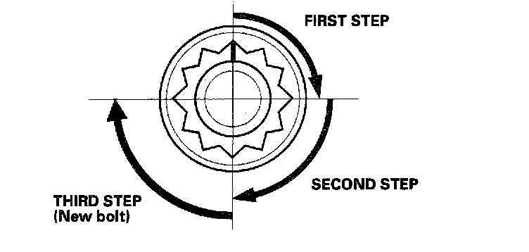
9. Tighten all cylinder head bolts in two steps (90° per step). If you are using a new cylinder head bolt, tighten the bolt an extra 90°.
10. Tighten the 8 mm bolts (A) to 22 Nm (2.2 kgf-m, 16 ft. lbs.).
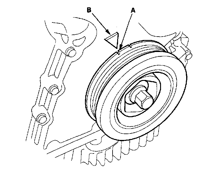
11. Make sure the crankshaft pulley is at Top Dead Center (TDC). Align the TDC mark (A) on the crankshaft pulley with the pointer (B) on the chain case.
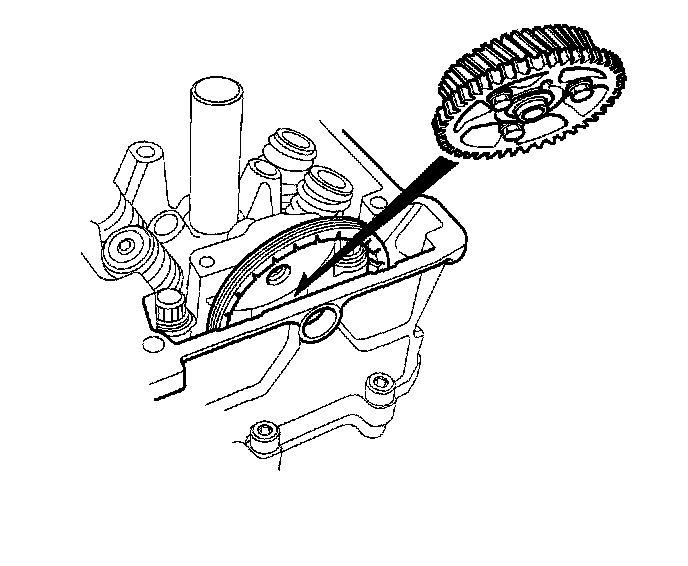
12. Place the idler gear/idler gear collar assembly into the cylinder head.
13. Install the cam chain on the sprocket, then fit the idler gear collar into the cylinder head.

14. Turn the idler gear counterclockwise to relieve cam chain free play, and check the alignment of the TDC marks (A) on the cam chain sprocket with the cylinder head surface. If the cam chain sprocket is not positioned at TDC, remove the idler gear from the cylinder head and reposition the cam chain to bring the cam chain sprocket to TDC.

15. Apply engine oil to the idler gear center bolt threads (A). Install a new O-ring (C) on the bolt.
16. Install the washer (B) on the idler gear, and tighten the idler gear center bolt.
17. Clamp the cam chain auto-tensioner in a soft-jawed vise.
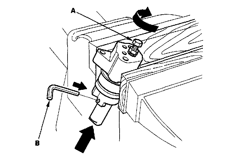
18. Turn the 5 x 0.8 mm bolt (A) clockwise to compress the bottom of the auto-tensioner, then insert the set pin (B), P/N 14511-PCX-005.
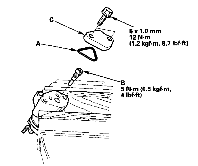
19. Remove the 5 x 0.8 mm bolt from the maintenance hole. Install a new O-ring (A), then install the nozzle (B) and end cover (c).
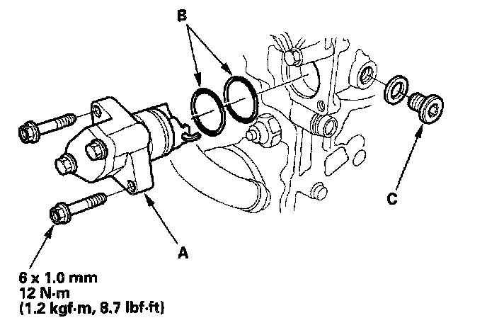
20. Install the cam chain auto-tensioner (A) in the cylinder head with new O-rings (B).
21. Remove the maintenance bolt (c) from the cylinder head.
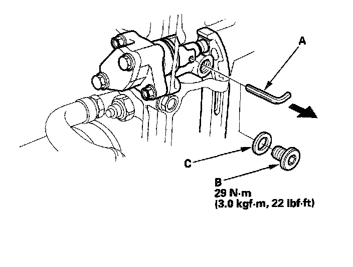
22. Remove the set pin (A) from the cam chain auto-tensioner. Reinstall the maintenance bolt (B) with new washer (C).
23. Install the rocker arm assembly.
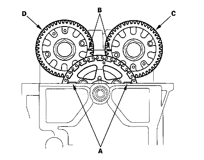
24. Check the alignment of the TDC marks (A) on the cam chain sprocket with the cylinder head surface.
25. Align the TDC marks (B) on the intake camshaft gear (C) and the exhaust camshaft gear (D), and install the camshafts.
26. Apply engine oil to the bolt threads of all the camshaft holder bolts.
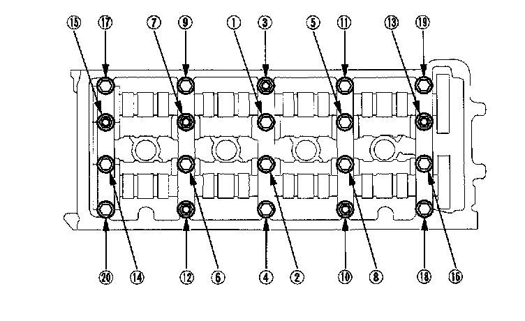
27. Put the camshaft holders on the cylinder head, then tighten all bolts to 22 Nm (2.2 kgf-m, 16 ft. lbs.).

28. Make sure the camshaft gears are at TDC.
29. Adjust the valve clearance.
30. Install the cylinder head cover.
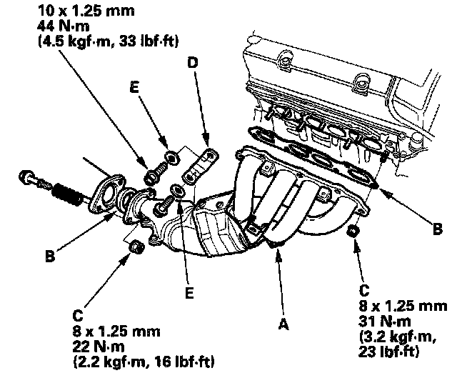
31. Install the exhaust manifold (A) using new gaskets (B) and new self locking nuts (C)
32. Install the exhaust manifold bracket (D). Make sure the smooth sides of the washers (E) face the exhaust manifold bracket.
33. Put the exhaust manifold cover on the exhaust manifold.
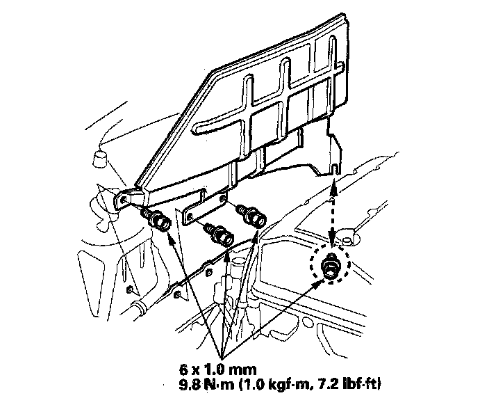
34. Install the heat shield.

35. Tighten the four bolts securing the exhaust manifold cover.
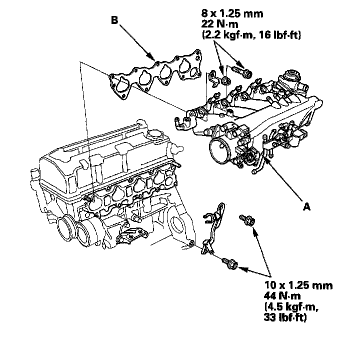
36. Install the intake manifold (A) with a new gasket (B).
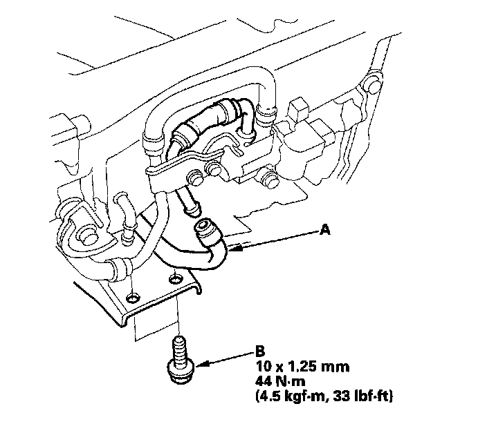
37. Install the water bypass hose (A), and tighten the two bolts (B) securing the intake manifold bracket.
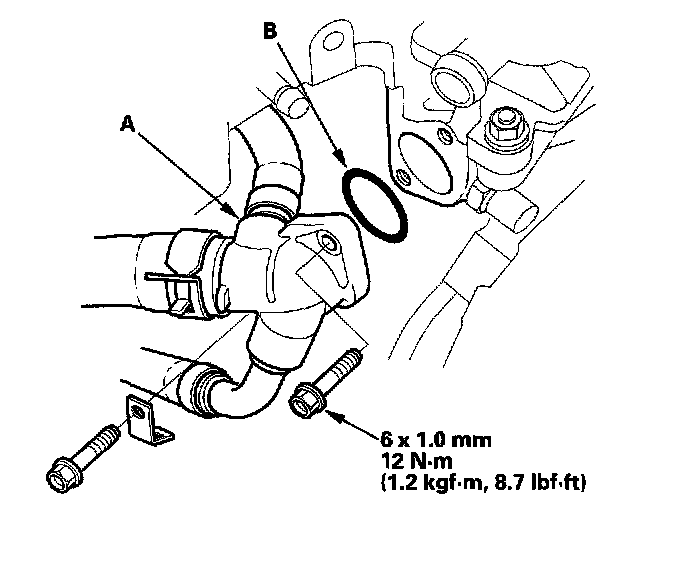
38. Install the water outlet cover (A) with a new O-ring (B).
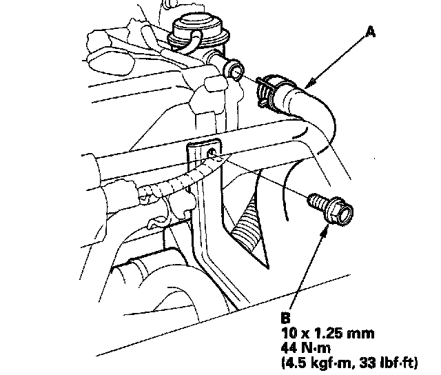
39. Install the air hose (A), and tighten the bolt (B) securing the intake manifold bracket.
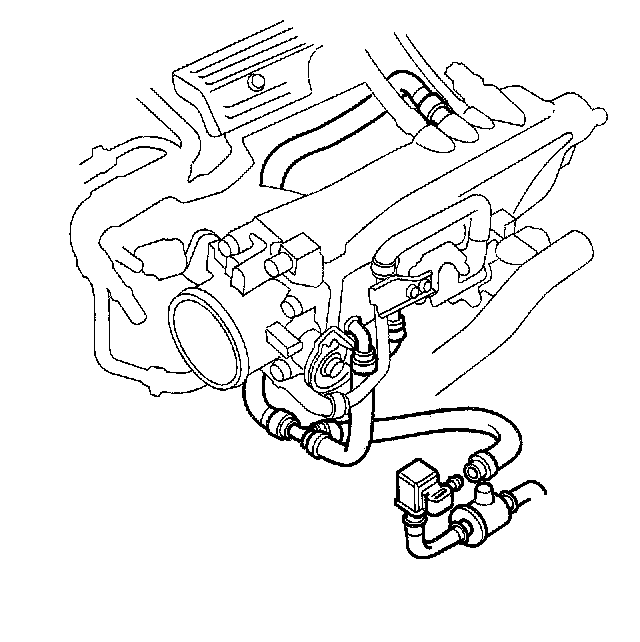
40. Install the Evaporative Emission (EVAP) control canister hose.

41. Install the brake booster vacuum hose (A), fuel return hose (B) and fuel feed hose (C), using new washers (D).
42. Install the alternator-compressor belt.
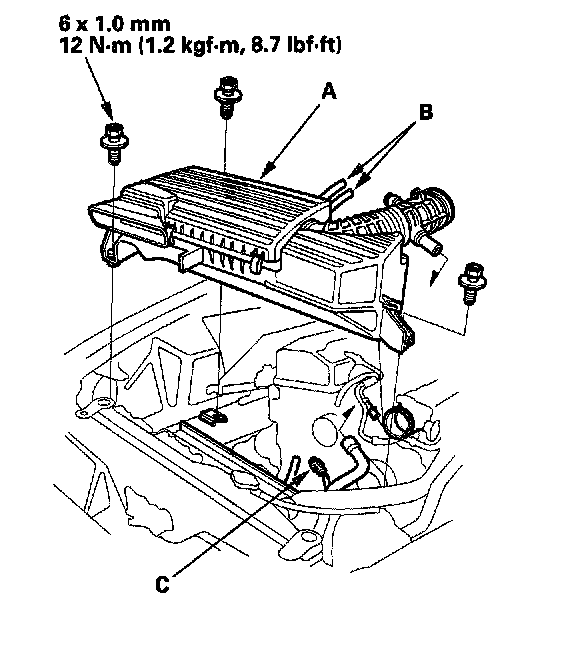
43. Install the air cleaner housing/intake air duct assembly (A), then install the vacuum hoses (B). Connect the air control solenoid valve connector (C).
44. Install the throttle cable, then adjust the cable.
45. After installation, check that all tubes, hoses and connectors are installed correctly.
46. After assembly, wait at least 30 minutes before filling the engine with oil.
47. Refill the radiator with engine coolant, and bleed air from the cooling system with the heater valve open.
48. Inspect for fuel leaks. Turn the ignition switch ON (II) (do not operate the starter) so that the fuel pump runs for about 2 seconds and pressurizes the fuel line. Repeat this operation two or three times, then check for fuel leakage at any point in the fuel line.
49. Inspect the idle speed.
50. Inspect the ignition timing.
51. Enter the anti-theft code for the radio, then enter the customer's radio station presets.
1. Measure the diameter of each cylinder head bolt at point A and point B. If either diameter is less than 11.5 mm (0.45 inch). replace the cylinder head bolt.
2. Clean the cylinder head and block surfaces.
3. Apply liquid gasket, part No. 08718-0009, to the shaded areas (A) of the cylinder head gasket mating surface of the block and chain case.
4. Install the dowel pins (A) and the new cylinder head gasket (B).
5. Apply liquid gasket, part No. 08718-0009, to the cylinder head mating surface of the block and chain case within 5 mm of the edge of the cylinder head Basket.
6. Install the cylinder head on the block.
7. Apply engine oil to the threads and under the heads of all the cylinder head bolts.
8. Tighten the cylinder head bolts in sequence to 29 Nm (3.0 kgf-m, 22 ft. lbs.). Use a beam-type torque wrench. When using a preset-type torque wrench, be sure to tighten slowly and do not overtighten. If a bolt makes any noise while you are torquing it, loosen the bolt an retighten it.
9. Tighten all cylinder head bolts in two steps (90° per step). If you are using a new cylinder head bolt, tighten the bolt an extra 90°.
10. Tighten the 8 mm bolts (A) to 22 Nm (2.2 kgf-m, 16 ft. lbs.).
11. Make sure the crankshaft pulley is at Top Dead Center (TDC). Align the TDC mark (A) on the crankshaft pulley with the pointer (B) on the chain case.
12. Place the idler gear/idler gear collar assembly into the cylinder head.
13. Install the cam chain on the sprocket, then fit the idler gear collar into the cylinder head.
14. Turn the idler gear counterclockwise to relieve cam chain free play, and check the alignment of the TDC marks (A) on the cam chain sprocket with the cylinder head surface. If the cam chain sprocket is not positioned at TDC, remove the idler gear from the cylinder head and reposition the cam chain to bring the cam chain sprocket to TDC.
15. Apply engine oil to the idler gear center bolt threads (A). Install a new O-ring (C) on the bolt.
16. Install the washer (B) on the idler gear, and tighten the idler gear center bolt.
17. Clamp the cam chain auto-tensioner in a soft-jawed vise.
18. Turn the 5 x 0.8 mm bolt (A) clockwise to compress the bottom of the auto-tensioner, then insert the set pin (B), P/N 14511-PCX-005.
19. Remove the 5 x 0.8 mm bolt from the maintenance hole. Install a new O-ring (A), then install the nozzle (B) and end cover (c).
20. Install the cam chain auto-tensioner (A) in the cylinder head with new O-rings (B).
21. Remove the maintenance bolt (c) from the cylinder head.
22. Remove the set pin (A) from the cam chain auto-tensioner. Reinstall the maintenance bolt (B) with new washer (C).
23. Install the rocker arm assembly.
24. Check the alignment of the TDC marks (A) on the cam chain sprocket with the cylinder head surface.
25. Align the TDC marks (B) on the intake camshaft gear (C) and the exhaust camshaft gear (D), and install the camshafts.
26. Apply engine oil to the bolt threads of all the camshaft holder bolts.
27. Put the camshaft holders on the cylinder head, then tighten all bolts to 22 Nm (2.2 kgf-m, 16 ft. lbs.).
28. Make sure the camshaft gears are at TDC.
29. Adjust the valve clearance.
30. Install the cylinder head cover.
31. Install the exhaust manifold (A) using new gaskets (B) and new self locking nuts (C)
32. Install the exhaust manifold bracket (D). Make sure the smooth sides of the washers (E) face the exhaust manifold bracket.
33. Put the exhaust manifold cover on the exhaust manifold.
34. Install the heat shield.
35. Tighten the four bolts securing the exhaust manifold cover.
36. Install the intake manifold (A) with a new gasket (B).
37. Install the water bypass hose (A), and tighten the two bolts (B) securing the intake manifold bracket.
38. Install the water outlet cover (A) with a new O-ring (B).
39. Install the air hose (A), and tighten the bolt (B) securing the intake manifold bracket.
40. Install the Evaporative Emission (EVAP) control canister hose.
41. Install the brake booster vacuum hose (A), fuel return hose (B) and fuel feed hose (C), using new washers (D).
42. Install the alternator-compressor belt.
43. Install the air cleaner housing/intake air duct assembly (A), then install the vacuum hoses (B). Connect the air control solenoid valve connector (C).
44. Install the throttle cable, then adjust the cable.
45. After installation, check that all tubes, hoses and connectors are installed correctly.
46. After assembly, wait at least 30 minutes before filling the engine with oil.
47. Refill the radiator with engine coolant, and bleed air from the cooling system with the heater valve open.
48. Inspect for fuel leaks. Turn the ignition switch ON (II) (do not operate the starter) so that the fuel pump runs for about 2 seconds and pressurizes the fuel line. Repeat this operation two or three times, then check for fuel leakage at any point in the fuel line.
49. Inspect the idle speed.
50. Inspect the ignition timing.
51. Enter the anti-theft code for the radio, then enter the customer's radio station presets.
Factory Service Tools
Use the Manual With the Right Hardware
Pair factory procedures with proven DIY tools so the instructions are easier to execute.
Disclosure: Verified tool recommendations may earn an affiliate commission at no cost to you.
When to See a Mechanic
Stop DIY work and contact a certified mechanic immediately if any of the following apply:
- • You smell fuel, burning insulation, or see smoke.
- • Brakes feel soft, pull hard to one side, or make grinding noises.
- • The engine overheats, stalls repeatedly, or misfires under load.
- • You are missing required tools, torque specs, or safe lifting equipment.
- • You are not confident in the next step or safety outcome.
Rather have a pro handle this?
A certified mobile mechanic comes to your home or office. They bring the tools, you stay comfortable. No tow truck, no waiting room, no surprises.
Comes to youSame-day available12-month warranty
Get a Free QuoteNo obligation. See pricing before you book.