
Safety Warning
DIY auto repair can cause serious injury, fire, or vehicle damage. These guides are for informational purposes only. Always follow OEM torque specs, wear PPE, and consult a certified mechanic if you are unsure. You are solely responsible for your safety.
1990 Geo Tracker L4-1590cc 1.6LFACTORY OEM SERVICE PROCEDURE
Compressor Overhaul
Remove or Disconnect
Tools Required:
J 9393-A Seal Seat Remover
J 34878 Pressure Plate Remover
1. Magnetic clutch.
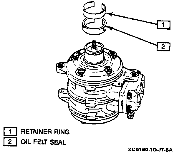
2. Oil felt from shaft. Pry off with screwdriver.
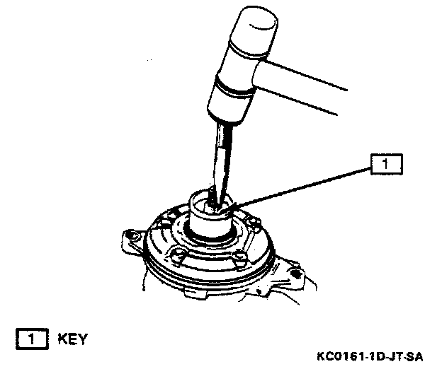
3. Drive key from shaft using a hammer and punch.
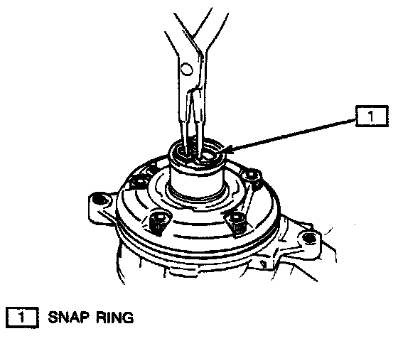
4. Snap ring using appropriate snap ring pliers.
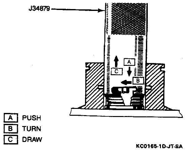
^ Apply compressor oil to inner bore to ease disassembly.
5. Seal seat, using a J 9393-A seal seat remover.
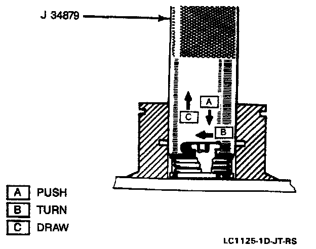
6. Shaft seal, using a 3 34879 shaft seal remover.
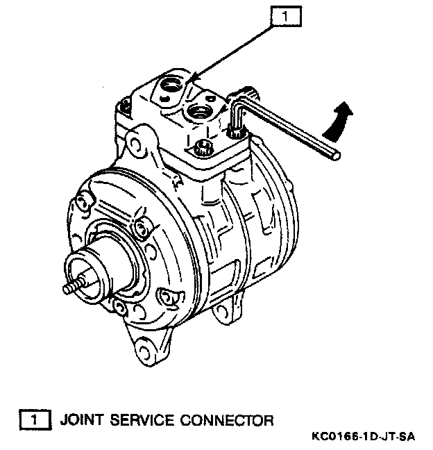
7 Four Allen-head bolts and joint service connector.
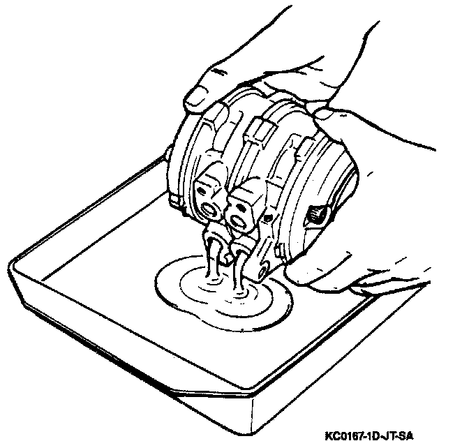
^ Drain compressor oil into a container and save.
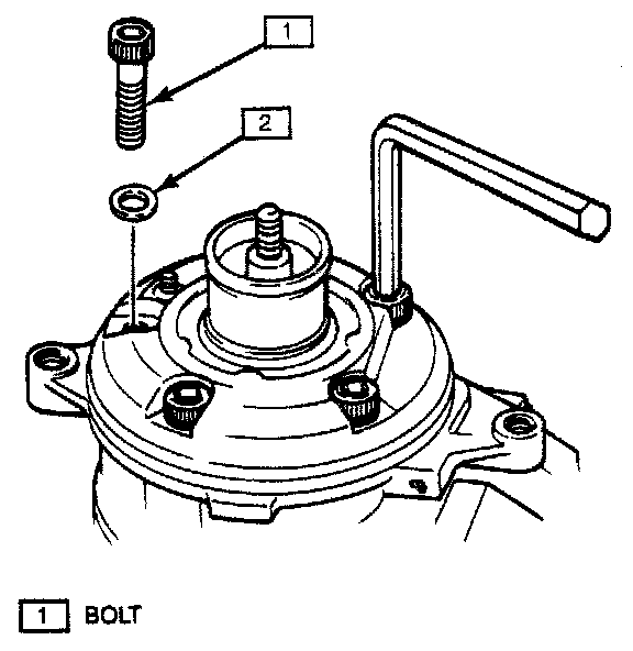
8. Five Allen-head bolts and washers securing front compressor housing.
NOTICE: Do not reuse 5 front housing washers.
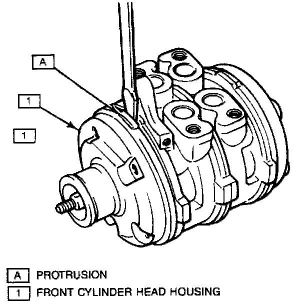
9. Front housing; pry off with a screwdriver.
10. Front gasket and reed valve.
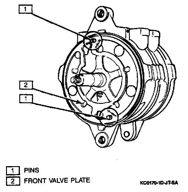
11. Two pins from front of compressor and valve plate.
12. Front suction valve.
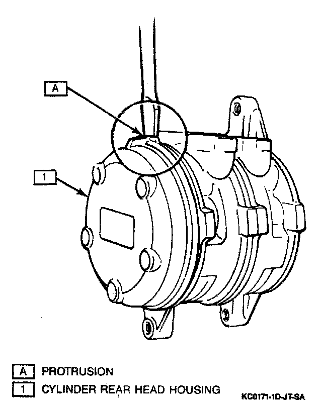
13. Rear compressor housing; pry off with a screwdriver.
NOTICE: Be careful not to damage or scratch sealing surfaces of the front and rear housings.
14. Rear gasket and reed valve.
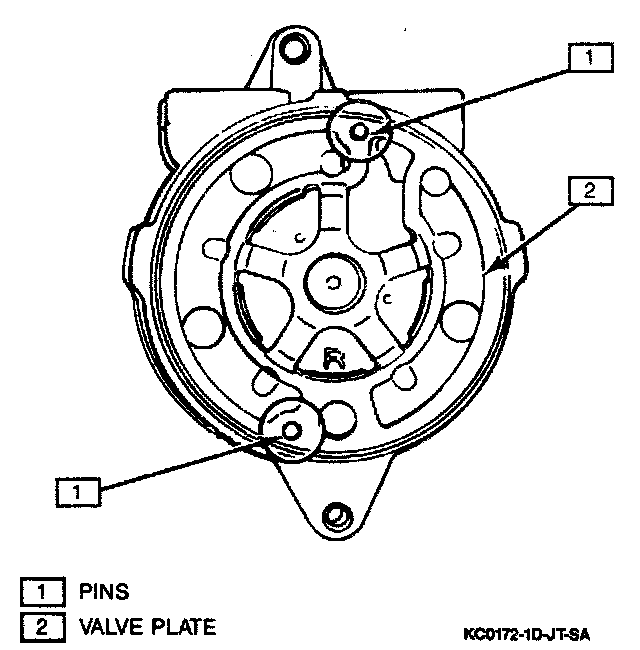
15. Two pins from rear of compressor and valve plate.
16. Rear suction plate.
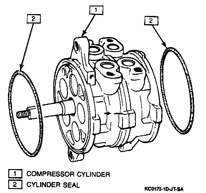
17. Front and rear cylinder seals and discard them.
Important
^ Do not disassemble the compressor any further. The compressor cylinder (subpump assembly) is replaced as a whole unit.
Important
^ Clean all compressor parts with solvent and apply compressor oil to them.
Install or Connect
Tool Required:
J 34879 Shaft Seal Remover
J 34880 Key Presser
NOTICE: Do not reuse shaft seal gasket O-rings, front or rear cylinder seals, or washers. Use new washers and a compressor gasket set.
Important
^ Before beginning reassembly procedures, make sure that all parts are clean and that the work area is clean.
1. New cylinder seal to rear of compressor. Lubricate seal with compressor oil.
2. Two pins on rear cylinder.
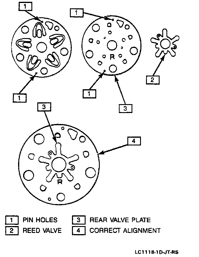
3. Suction valve, valve plate, and reed valve to rear of compressor; lining up the plates with the 2 pins.
Important
^ The front and rear suction and reed valves are identical. The front and rear valve plates are marked "F" and "R".
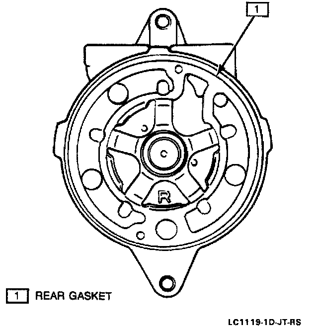

4. New rear gasket; lubricate with compressor oil prior to installation.
Important
^ The front and rear and gaskets are different. Do not interchange them.
^ Assemble gaskets so that their protruded surfaces face upward.
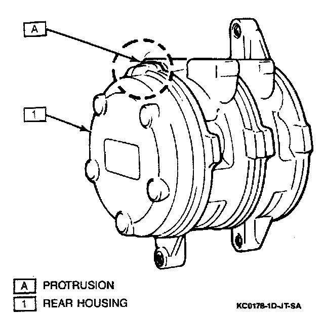
5. Rear housing to compressor.
6. New cylinder seal to front of compressor. Lubricate seal with compressor oil.
7. Two pins on front cylinder.
8. Suction valve, valve plate, and reed valve to front of compressor; lining up the plates with the 2 pins.
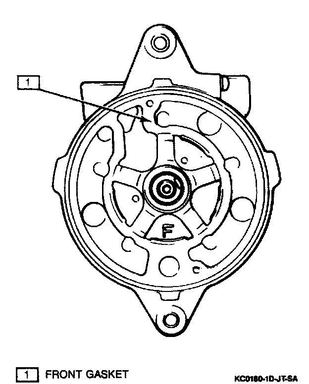
9. New front compressor gasket; lubricate with compressor oil prior to installation.
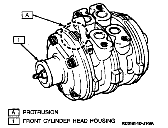
10. Front compressor housing and 5 through bolts with new washers.
Tighten
^ Through bolts to 27 N.m (20 lb.ft.).
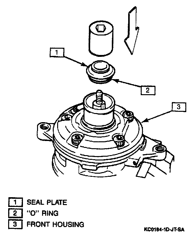
11. Shaft seal.
A. Apply compressor oil to shaft seal and bore prior to installation.
B. Fit the shaft seal to a J 34879 shaft seal remover/installer.
C. Shaft seal and tool; turn the 3 34879 to the left while pressing slightly. Then remove the tool.
13. New O-ring using snap ring pliers.
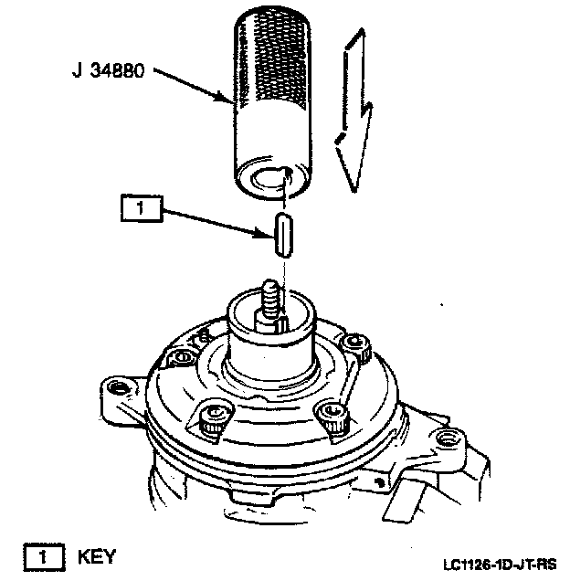
14. Key into shaft groove using a 3 34880 key presser.
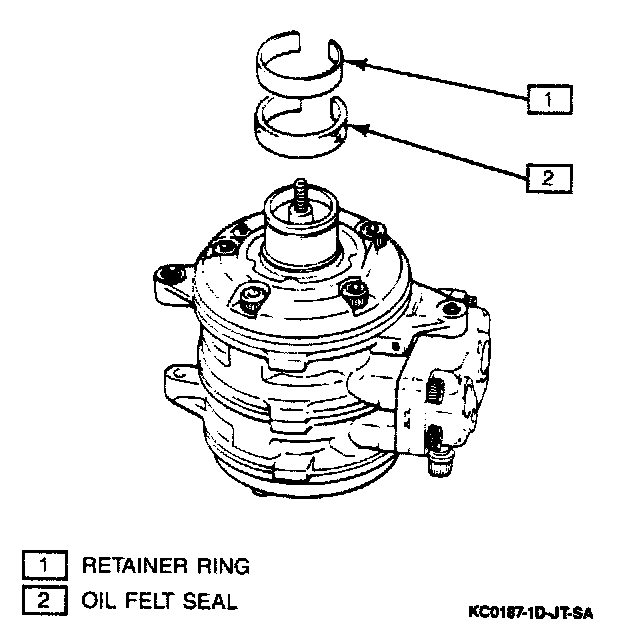
15. New oil felt inside the bore.
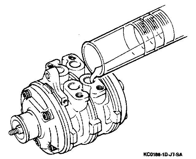
^ Pour compressor oil into compressor. Add the same amount of oil removed at the beginning of the overhaul procedure.
Important
^ If a new compressor is being installed, it is shipped from the factory with 80 cc (4.9 cu. in.) of compressor oil in it. Drain 40 cc (2.45 cu. in.) of oil from the new compressor before installation, as that much oil remains in other components within the vehicle's refrigeration system.
Tighten
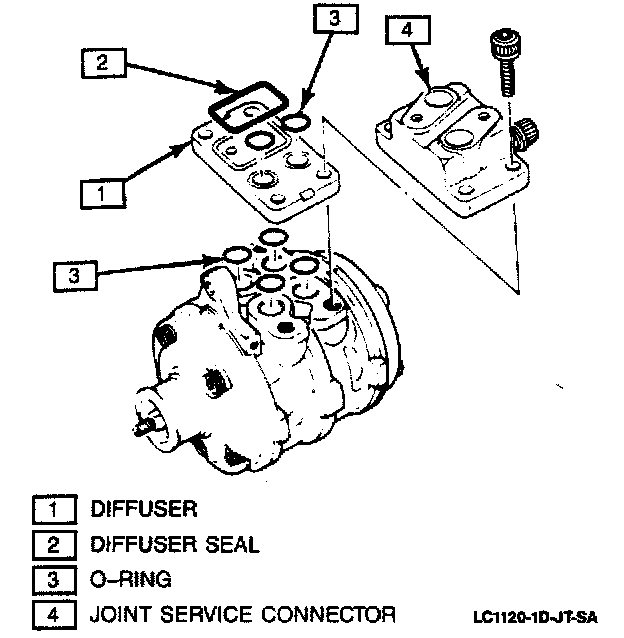
^ Four service connector bolts to 27 N.m (20 lb. ft.).
Important
^ The suction port has a larger internal opening than the discharge port. The O-rings are not interchangeable.
17. Magnetic clutch.
Inspect
^ Shaft rotating torque. Torque should be less than 3 N.m (27 lb. in.).
Tools Required:
J 9393-A Seal Seat Remover
J 34878 Pressure Plate Remover
1. Magnetic clutch.
Oil Felt Removal:
2. Oil felt from shaft. Pry off with screwdriver.
Drive Key Removal:
3. Drive key from shaft using a hammer and punch.
Removing Snap Ring:
4. Snap ring using appropriate snap ring pliers.
Applying Compressor Oil:
^ Apply compressor oil to inner bore to ease disassembly.
5. Seal seat, using a J 9393-A seal seat remover.
Shaft Seal Removal:
6. Shaft seal, using a 3 34879 shaft seal remover.
Joint Service Valve Connector:
7 Four Allen-head bolts and joint service connector.
Drain Compressor:
^ Drain compressor oil into a container and save.
Front Housing Bolts:
8. Five Allen-head bolts and washers securing front compressor housing.
NOTICE: Do not reuse 5 front housing washers.
Prying Off Front Housing:
9. Front housing; pry off with a screwdriver.
10. Front gasket and reed valve.
Front Valve Plate:
11. Two pins from front of compressor and valve plate.
12. Front suction valve.
Prying Off Rear Housing:
13. Rear compressor housing; pry off with a screwdriver.
NOTICE: Be careful not to damage or scratch sealing surfaces of the front and rear housings.
14. Rear gasket and reed valve.
Rear Valve Plate:
15. Two pins from rear of compressor and valve plate.
16. Rear suction plate.
Front and Rear Cylinder Seals:
17. Front and rear cylinder seals and discard them.
Important
^ Do not disassemble the compressor any further. The compressor cylinder (subpump assembly) is replaced as a whole unit.
Important
^ Clean all compressor parts with solvent and apply compressor oil to them.
Install or Connect
Tool Required:
J 34879 Shaft Seal Remover
J 34880 Key Presser
NOTICE: Do not reuse shaft seal gasket O-rings, front or rear cylinder seals, or washers. Use new washers and a compressor gasket set.
Important
^ Before beginning reassembly procedures, make sure that all parts are clean and that the work area is clean.
1. New cylinder seal to rear of compressor. Lubricate seal with compressor oil.
2. Two pins on rear cylinder.
Compressor Valves:
3. Suction valve, valve plate, and reed valve to rear of compressor; lining up the plates with the 2 pins.
Important
^ The front and rear suction and reed valves are identical. The front and rear valve plates are marked "F" and "R".
Rear Gasket:
Front And Rear Compressor Gaskets:
4. New rear gasket; lubricate with compressor oil prior to installation.
Important
^ The front and rear and gaskets are different. Do not interchange them.
^ Assemble gaskets so that their protruded surfaces face upward.
Rear Housing Installation:
5. Rear housing to compressor.
6. New cylinder seal to front of compressor. Lubricate seal with compressor oil.
7. Two pins on front cylinder.
8. Suction valve, valve plate, and reed valve to front of compressor; lining up the plates with the 2 pins.
Front Gasket:
9. New front compressor gasket; lubricate with compressor oil prior to installation.
Front Housing Installation:
10. Front compressor housing and 5 through bolts with new washers.
Tighten
^ Through bolts to 27 N.m (20 lb.ft.).
Seal Plate Installation:
11. Shaft seal.
A. Apply compressor oil to shaft seal and bore prior to installation.
B. Fit the shaft seal to a J 34879 shaft seal remover/installer.
C. Shaft seal and tool; turn the 3 34879 to the left while pressing slightly. Then remove the tool.
13. New O-ring using snap ring pliers.
Key Installation:
14. Key into shaft groove using a 3 34880 key presser.
Oil Felt Installation:
15. New oil felt inside the bore.
Adding Oil To Compressor:
^ Pour compressor oil into compressor. Add the same amount of oil removed at the beginning of the overhaul procedure.
Important
^ If a new compressor is being installed, it is shipped from the factory with 80 cc (4.9 cu. in.) of compressor oil in it. Drain 40 cc (2.45 cu. in.) of oil from the new compressor before installation, as that much oil remains in other components within the vehicle's refrigeration system.
Service Valve Installation:
Tighten
^ Four service connector bolts to 27 N.m (20 lb. ft.).
Important
^ The suction port has a larger internal opening than the discharge port. The O-rings are not interchangeable.
17. Magnetic clutch.
Inspect
^ Shaft rotating torque. Torque should be less than 3 N.m (27 lb. in.).
Factory Service Tools
Use the Manual With the Right Hardware
Pair factory procedures with proven DIY tools so the instructions are easier to execute.
Disclosure: Verified tool recommendations may earn an affiliate commission at no cost to you.
When to See a Mechanic
Stop DIY work and contact a certified mechanic immediately if any of the following apply:
- • You smell fuel, burning insulation, or see smoke.
- • Brakes feel soft, pull hard to one side, or make grinding noises.
- • The engine overheats, stalls repeatedly, or misfires under load.
- • You are missing required tools, torque specs, or safe lifting equipment.
- • You are not confident in the next step or safety outcome.