
Safety Warning
DIY auto repair can cause serious injury, fire, or vehicle damage. These guides are for informational purposes only. Always follow OEM torque specs, wear PPE, and consult a certified mechanic if you are unsure. You are solely responsible for your safety.
1989 Geo Tracker L4-1590cc 1.6LFACTORY OEM SERVICE PROCEDURE
Disassembly/Assembly Procedure
Disassemble
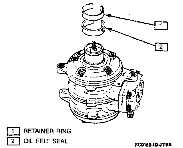
1. Using a screwdriver, gently pry out oil felt.
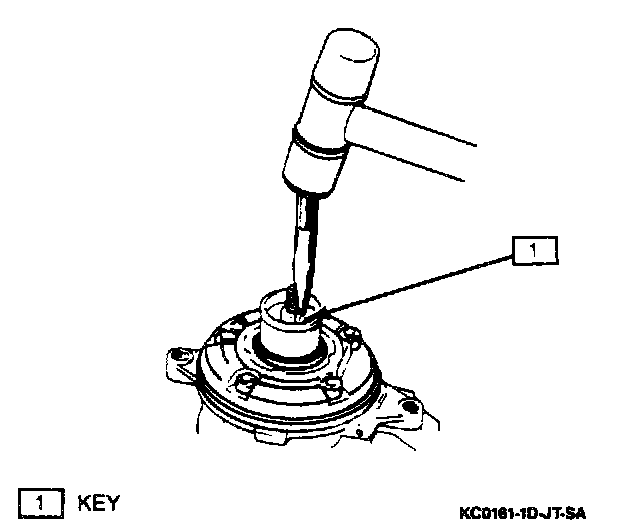
2. Use hammer and punch to drive key away from the shaft.
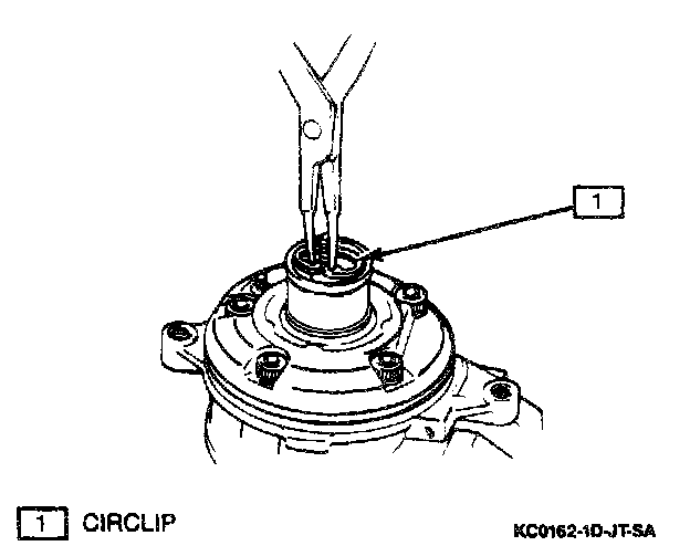
3. Use appropriate snap ring pliers to remove snap ring from compressor ring shaft.
Install or Connect
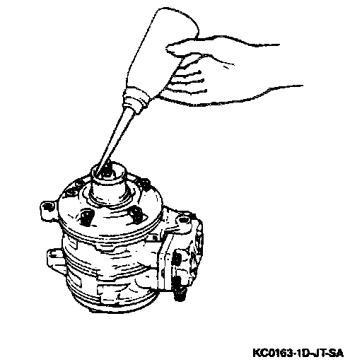
4. Apply a small amount of refrigerant oil to compressor housing inner bore.
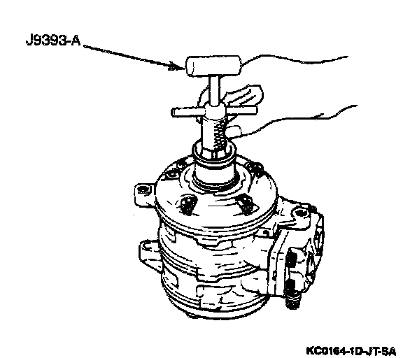
5. Using Seal Seat Remover J9393-A, remove seal seat from compressor housing.
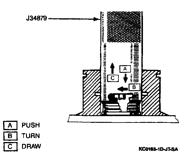
6. Using Shaft Seal Remover J34879, remove shaft seal from compressor housing.
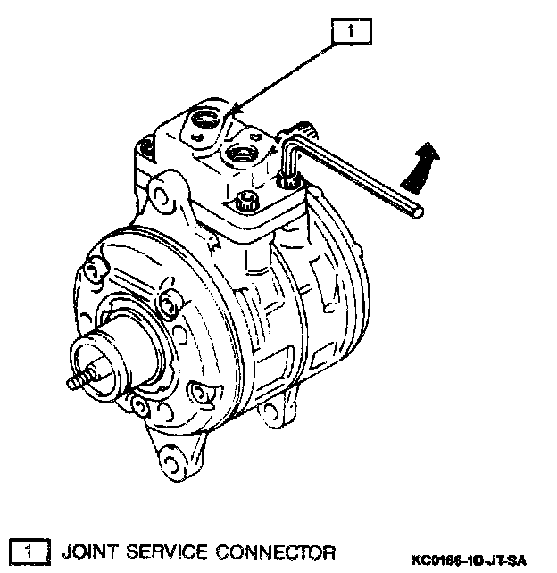
7. Service valve assembly from compressor housing.
8. "O" rings from service valve assembly and discard them.
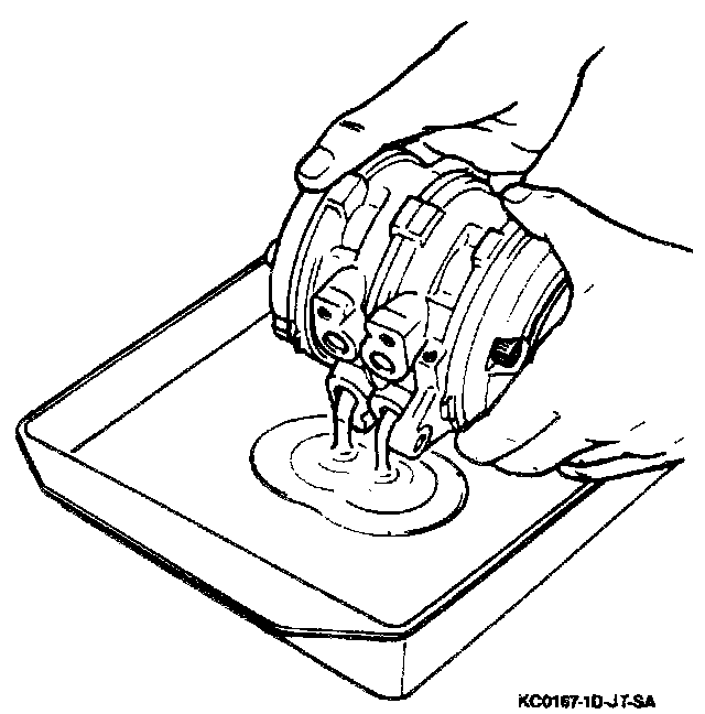
9. Drain oil into an appropriate container.
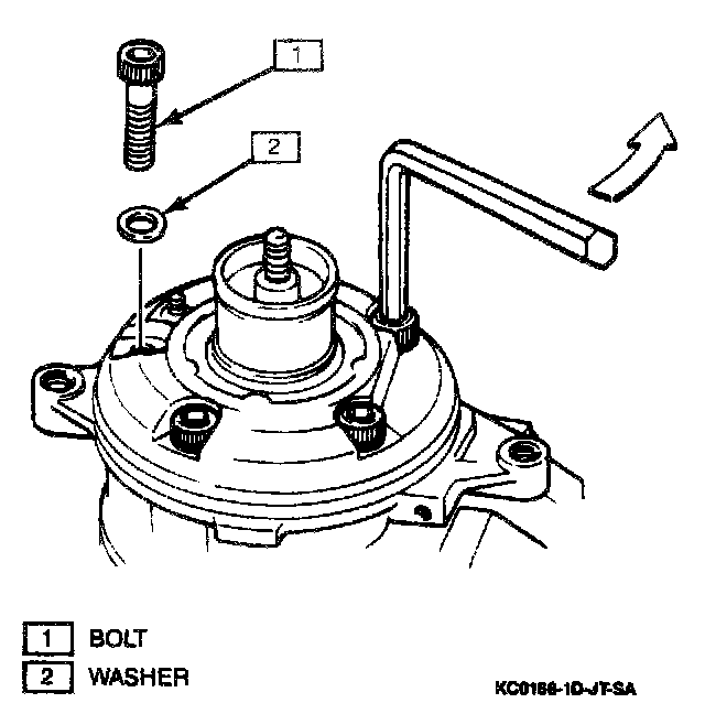
10. Front housing attaching bolts and washers.
NOTICE Do not reuse washers, discard and replace with new ones.
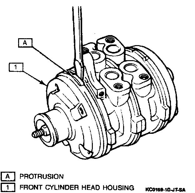
11. Using a screwdriver, pry front housing from compressor assembly at protrusion).
NOTICE Care must be exercised not to damage sealing surface of front housing during removal.
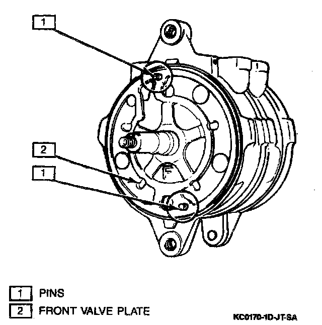
12. Front valve plate and two pins from cylinder block.
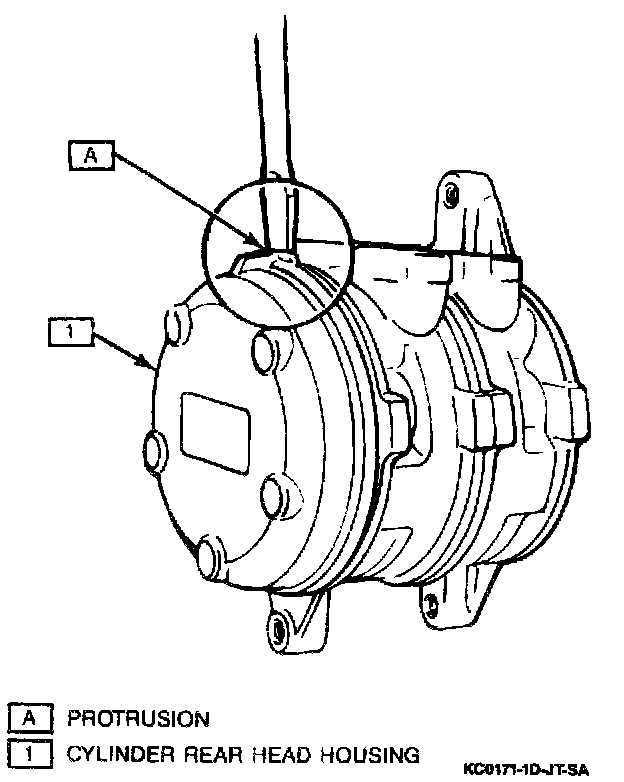
13. Rear housing by prying at protrusion.
NOTICE Care must be exercised not to damage sealing surface of rear housing during removal.
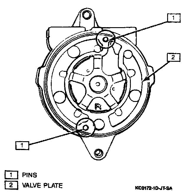
14. Rear valve plate and pins from cylinder block.
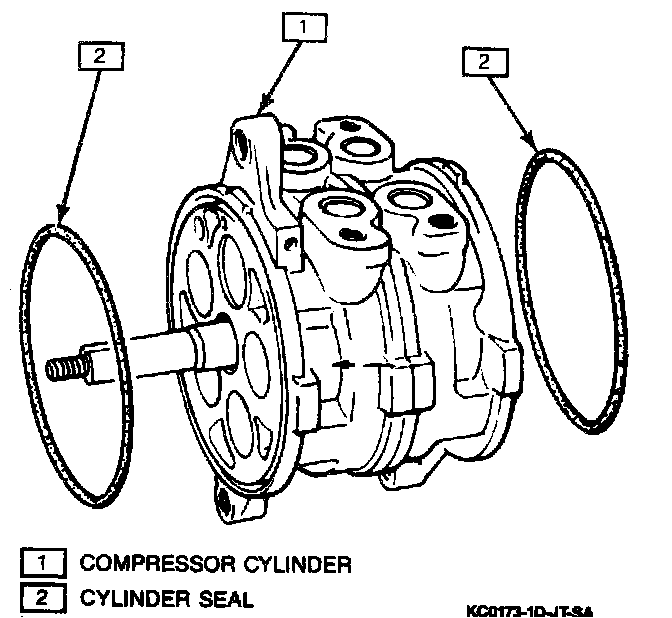
15. Front and rear "O" rings from cylinder block and discard them.
Assemble
Important
^ Do not reuse shaft seal gasket, "O" rings, or washers. Use overhaul gasket set.
^ Before starting assembly procedure, make sure all parts and work area are clean.
1. Rear valve plate to cylinder block.
2. Two pins in rear of cylinder block.
3. Lubricate new "O" ring with refrigerant oil and install to rear of cylinder block.
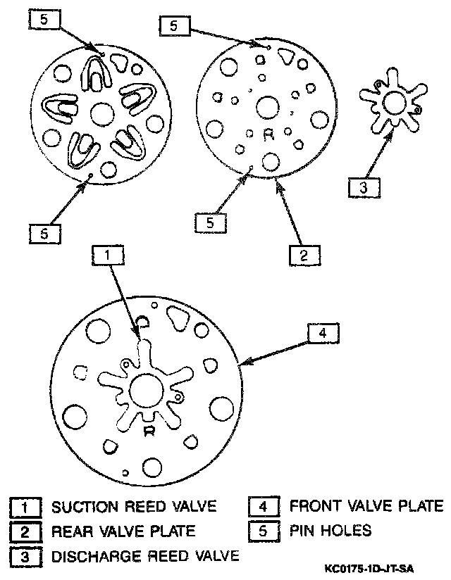
4. Suction reed valve, rear valve plate, and discharge reed valve onto cylinder block.
NOTICE
^ Front and rear reed valves (suction and discharge) are the same.
^ Rear valve plate if marked "R".
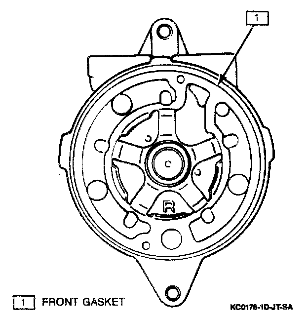
5. Lubricate rear gasket with refrigerant oil and install on rear valve plate.
Important
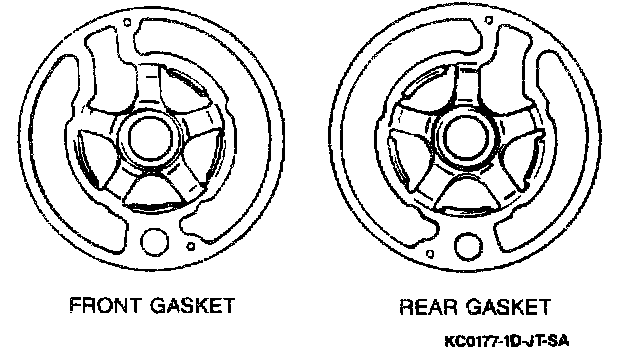
^ Front and rear gaskets are different, so do not interchange them.
^ Assemble gaskets so that their protruded surfaces face upward.
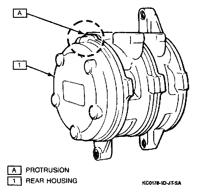
6. Rear housing to cylinder block with protrusion at the top.
7. Front valve plate to cylinder block.
8. Two pins in front of cylinder block.
9. Lubricate new "O" ring with refrigerant oil and install to front of cylinder block.
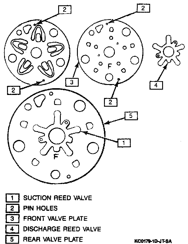
10. Suction reed valve, front valve plate, and discharge reed valve onto cylinder block.
NOTICE
^ Front and rear reed valves (suction and discharge) are the same.
^ Front valve plate is marked "F".
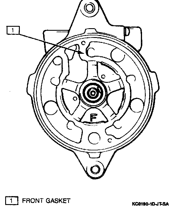
11. Lubricate front gasket with refrigerant oil and install valve plate.
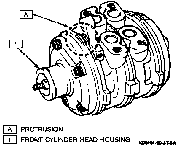
12. Front housing to cylinder block with protrusion at the top.
Tighten
^ Compressor housing thru bolts to 25 - 27 N.m (18.1 - 19.5 lb.ft.).
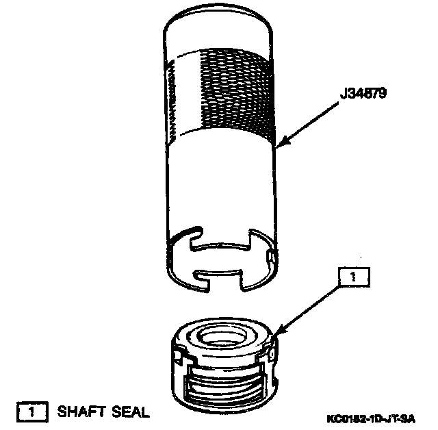
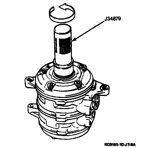
13. Lubricate shaft seal and bore with refrigerant oil and using Shaft Seal Installer J34879 insert seal into shaft turning slightly to the left to seat seal. Remove tool by gently pulling up.
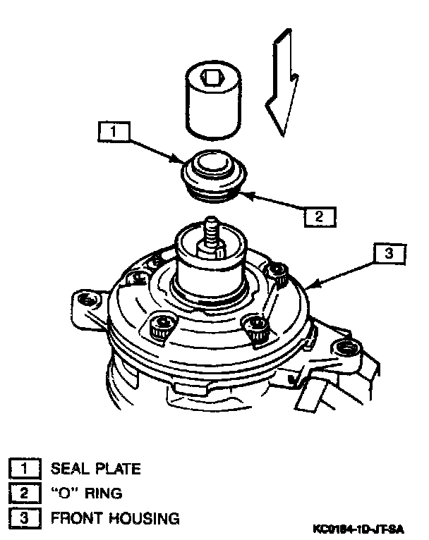
14. Lubricate seal plate with refrigerant oil and press into shaft by hand using an appropriate socket.
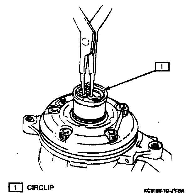
15. Using appropriate snap ring pliers, snap ring to compressor shaft.
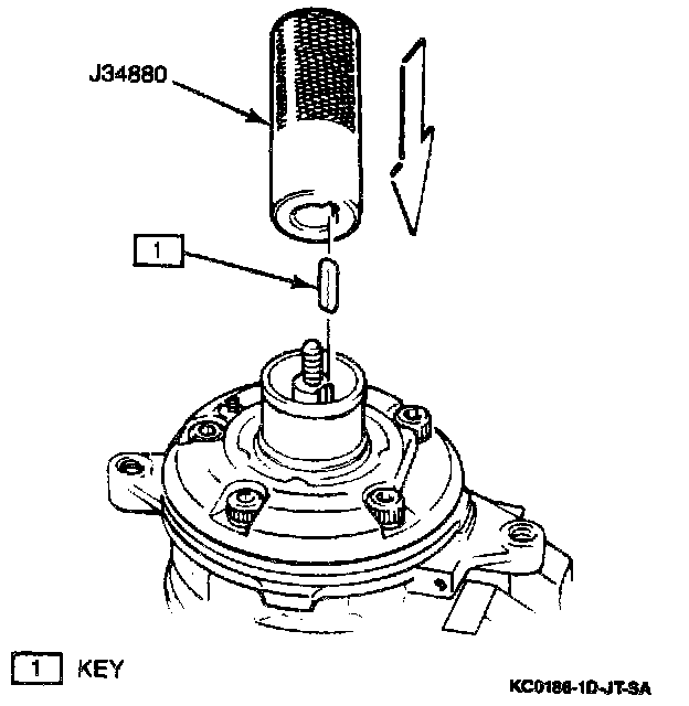
16. Key into shaft using Key Presser J 34880.
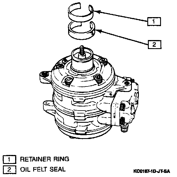
17. Oil felt to inside of compressor bore.
Measure
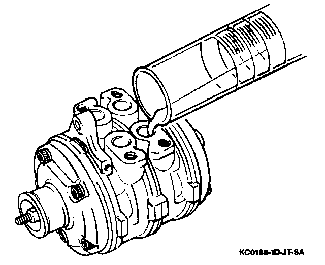
^ After compressor is overhauled and reassembled, 40cc (2.4 cu. in.) of refrigerant oil must be added to replace lost oil to the A/C system.
Important
^ If compressor assembly is replaced, 40cc (2.4 cu.in.) of oil must be drained before installation into the A/C system. Supplied from factory, the compressor is filled with 80cc (4.9 cu.in.) of oil. Failure to drain the specified quantity of oil prior to installation may overload the system decreasing cooling capacity and/or damaging system components.
18. Lubricate "O" rings with refrigerant oil and install into service valve assembly).
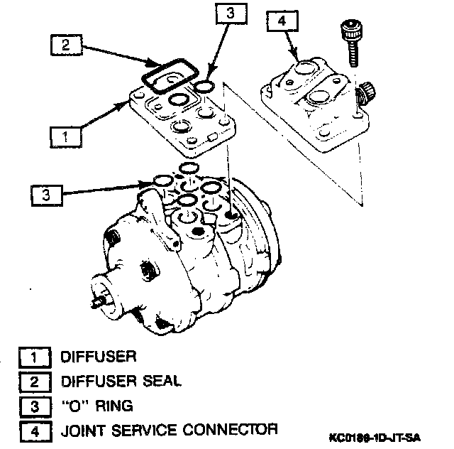
19. Service valve assembly.
Tighten
^ Service valve assembly attaching bolts to 25 - 27 N.m (18.1 - 19.5 lb.ft.).
NOTICE Suction port has a larger internal opening than the discharge port. Therefore, "O" rings cannot be interchanged.
Inspect
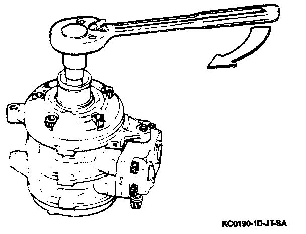
^ Shaft rotating torque is no greater than 3.0 N.m (2.2 lb.ft.).
Oil Pan Removal:
1. Using a screwdriver, gently pry out oil felt.
Shaft Key Removal:
2. Use hammer and punch to drive key away from the shaft.
Compressor Shaft Snap Ring Removal:
3. Use appropriate snap ring pliers to remove snap ring from compressor ring shaft.
Install or Connect
Compressor Inner Bore Oil Application:
4. Apply a small amount of refrigerant oil to compressor housing inner bore.
Seal Seat Removal:
5. Using Seal Seat Remover J9393-A, remove seal seat from compressor housing.
Shaft Seal Removal:
6. Using Shaft Seal Remover J34879, remove shaft seal from compressor housing.
Service Valve Assembly Removal:
7. Service valve assembly from compressor housing.
8. "O" rings from service valve assembly and discard them.
Compressor Oil Removal:
9. Drain oil into an appropriate container.
Front Housing Attaching Bolts Removal:
10. Front housing attaching bolts and washers.
NOTICE Do not reuse washers, discard and replace with new ones.
Front Housing Removal:
11. Using a screwdriver, pry front housing from compressor assembly at protrusion).
NOTICE Care must be exercised not to damage sealing surface of front housing during removal.
Front Valve Plate Removal:
12. Front valve plate and two pins from cylinder block.
Rear Housing Removal:
13. Rear housing by prying at protrusion.
NOTICE Care must be exercised not to damage sealing surface of rear housing during removal.
Front Housing Attaching Bolts Removal:
14. Rear valve plate and pins from cylinder block.
"O" Ring Removal:
15. Front and rear "O" rings from cylinder block and discard them.
Assemble
Important
^ Do not reuse shaft seal gasket, "O" rings, or washers. Use overhaul gasket set.
^ Before starting assembly procedure, make sure all parts and work area are clean.
1. Rear valve plate to cylinder block.
2. Two pins in rear of cylinder block.
3. Lubricate new "O" ring with refrigerant oil and install to rear of cylinder block.
Rear Valve Plate Installation:
4. Suction reed valve, rear valve plate, and discharge reed valve onto cylinder block.
NOTICE
^ Front and rear reed valves (suction and discharge) are the same.
^ Rear valve plate if marked "R".
5. Lubricate rear gasket with refrigerant oil and install on rear valve plate.
Important
^ Front and rear gaskets are different, so do not interchange them.
^ Assemble gaskets so that their protruded surfaces face upward.
Rear Housing Installation:
6. Rear housing to cylinder block with protrusion at the top.
7. Front valve plate to cylinder block.
8. Two pins in front of cylinder block.
9. Lubricate new "O" ring with refrigerant oil and install to front of cylinder block.
Front Valve Plate Installation:
10. Suction reed valve, front valve plate, and discharge reed valve onto cylinder block.
NOTICE
^ Front and rear reed valves (suction and discharge) are the same.
^ Front valve plate is marked "F".
Front Gasket Installation:
11. Lubricate front gasket with refrigerant oil and install valve plate.
Front Housing Installation:
12. Front housing to cylinder block with protrusion at the top.
Tighten
^ Compressor housing thru bolts to 25 - 27 N.m (18.1 - 19.5 lb.ft.).
Shaft Seal Installer J 34879:
Shaft Seal Installation:
13. Lubricate shaft seal and bore with refrigerant oil and using Shaft Seal Installer J34879 insert seal into shaft turning slightly to the left to seat seal. Remove tool by gently pulling up.
Seal Plate Installation:
14. Lubricate seal plate with refrigerant oil and press into shaft by hand using an appropriate socket.
Snap Ring Installation:
15. Using appropriate snap ring pliers, snap ring to compressor shaft.
16. Key into shaft using Key Presser J 34880.
Oil Felt Installation:
17. Oil felt to inside of compressor bore.
Measure
Adding Refrigerant Oil To Compressor:
^ After compressor is overhauled and reassembled, 40cc (2.4 cu. in.) of refrigerant oil must be added to replace lost oil to the A/C system.
Important
^ If compressor assembly is replaced, 40cc (2.4 cu.in.) of oil must be drained before installation into the A/C system. Supplied from factory, the compressor is filled with 80cc (4.9 cu.in.) of oil. Failure to drain the specified quantity of oil prior to installation may overload the system decreasing cooling capacity and/or damaging system components.
18. Lubricate "O" rings with refrigerant oil and install into service valve assembly).
Service Valve Installation:
19. Service valve assembly.
Tighten
^ Service valve assembly attaching bolts to 25 - 27 N.m (18.1 - 19.5 lb.ft.).
NOTICE Suction port has a larger internal opening than the discharge port. Therefore, "O" rings cannot be interchanged.
Inspect
Shaft Rotation Inspection:
^ Shaft rotating torque is no greater than 3.0 N.m (2.2 lb.ft.).
Factory Service Tools
Use the Manual With the Right Hardware
Pair factory procedures with proven DIY tools so the instructions are easier to execute.
Disclosure: Verified tool recommendations may earn an affiliate commission at no cost to you.
When to See a Mechanic
Stop DIY work and contact a certified mechanic immediately if any of the following apply:
- • You smell fuel, burning insulation, or see smoke.
- • Brakes feel soft, pull hard to one side, or make grinding noises.
- • The engine overheats, stalls repeatedly, or misfires under load.
- • You are missing required tools, torque specs, or safe lifting equipment.
- • You are not confident in the next step or safety outcome.