
Safety Warning
DIY auto repair can cause serious injury, fire, or vehicle damage. These guides are for informational purposes only. Always follow OEM torque specs, wear PPE, and consult a certified mechanic if you are unsure. You are solely responsible for your safety.
1989 Geo Spectrum L4-91.5 1.5LFACTORY OEM SERVICE PROCEDURE
Minor Compressor Repair Procedures
Removal
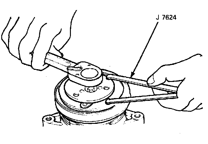
1. Using holder (J 7624) to prevent drive plate rotation, remove the bolt.
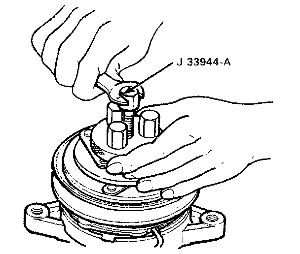
2. Using Puller (J 33944-A), remove the drive plate. Remove the shims from the compressor drive shaft or drive plate.

3. Remove the snap ring with external snap ring pliers and then remove the cover.
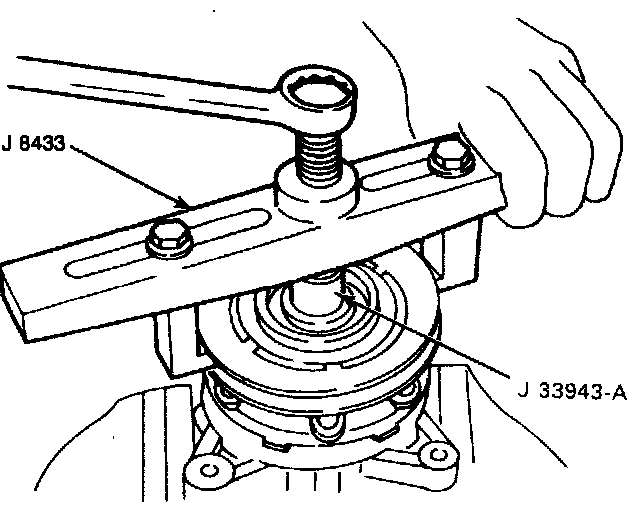
4. Remove the pulley assembly using pulley puller pilot (J 33943-A) and pulley puller (J 8433).
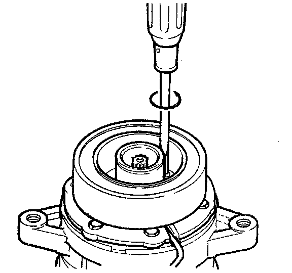
5. Remove the coil lead wire and coil by removing three screws.
Inspection
Drive Plate
If the frictional surface shows signs of damage due to excessive heat, the drive plate and pulley should be replaced.
Pulley Assembly
Check the appearance of the pulley assembly. If the frictional surface of the pulley shows signs of excessive grooving due to slippage, both the pulley and drive plate should be replaced. The frictional surfaces of the pulley assembly should be cleaned with a suitable solvent before reinstallation.
Coil
Check coil for loose connector or cracked insulation.
1. Install the coil to compressor (lead wire up) and tighten the mounting screws to 5.0 N.m (3.6 ft. lbs.).
2. Install the lead wire in the hole with the rubber holder.
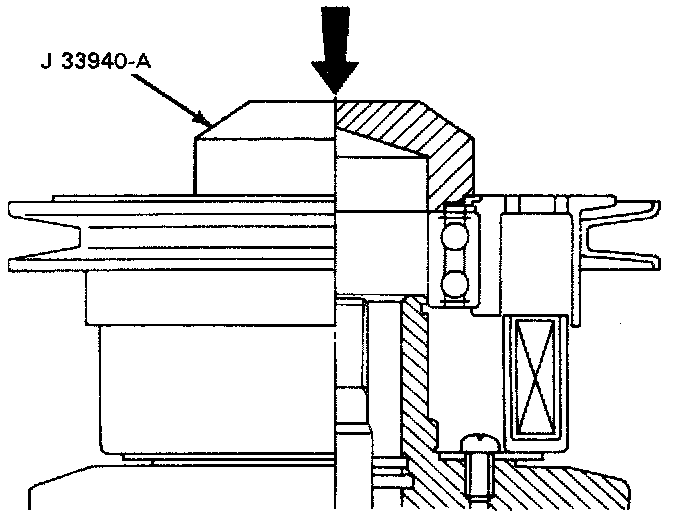
3. Install the pulley assembly using installer (J 33940-A), then install the cover and the snap ring.
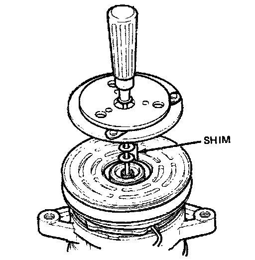
4. Install the drive plate to the compressor drive shaft, together with the original shim(s). Press the drive plate by hand.
5. Install the center bolt.
Using holder (J 7624) to prevent drive plate rotation, tighten the bolt to 15.0 N.m (11.0 ft. lbs.).
NOTICE: After tightening the bolt, check to be sure the pulley rotates smoothly.
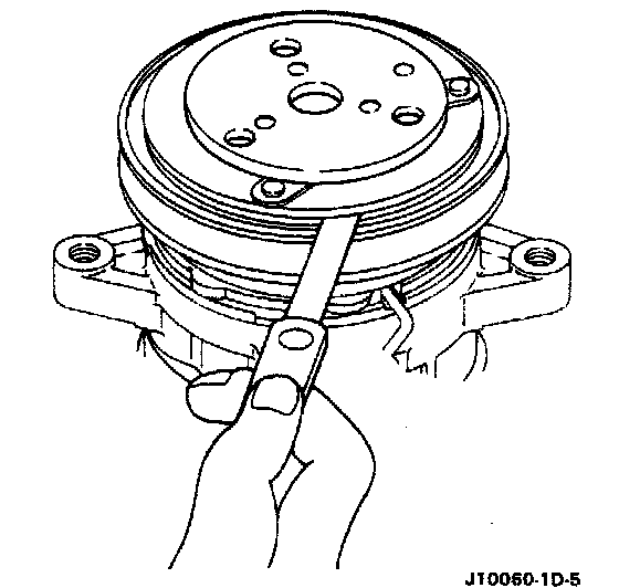
6. Check to be sure that the clutch clearance is between 0.3 - 0.6 mm (0.01- 0.02 in.). Adjust the clearance using shim(s) as necessary. Adjusting shims are available in the following thicknesses:
Thickness
^ 0.1 mm (0.0039 in.)
^ 0.3 mm (0.0118 in.)
^ 0.5 mm (0.0197 in.)
Clutch Holding Tool:
1. Using holder (J 7624) to prevent drive plate rotation, remove the bolt.
Clutch Puller:
2. Using Puller (J 33944-A), remove the drive plate. Remove the shims from the compressor drive shaft or drive plate.
Snap Ring Removal:
3. Remove the snap ring with external snap ring pliers and then remove the cover.
Pulley Removal:
4. Remove the pulley assembly using pulley puller pilot (J 33943-A) and pulley puller (J 8433).
Field Coil Removal:
5. Remove the coil lead wire and coil by removing three screws.
Inspection
Drive Plate
If the frictional surface shows signs of damage due to excessive heat, the drive plate and pulley should be replaced.
Pulley Assembly
Check the appearance of the pulley assembly. If the frictional surface of the pulley shows signs of excessive grooving due to slippage, both the pulley and drive plate should be replaced. The frictional surfaces of the pulley assembly should be cleaned with a suitable solvent before reinstallation.
Coil
Check coil for loose connector or cracked insulation.
1. Install the coil to compressor (lead wire up) and tighten the mounting screws to 5.0 N.m (3.6 ft. lbs.).
2. Install the lead wire in the hole with the rubber holder.
Pulley Installed:
3. Install the pulley assembly using installer (J 33940-A), then install the cover and the snap ring.
Adjusting Shims:
4. Install the drive plate to the compressor drive shaft, together with the original shim(s). Press the drive plate by hand.
5. Install the center bolt.
Using holder (J 7624) to prevent drive plate rotation, tighten the bolt to 15.0 N.m (11.0 ft. lbs.).
NOTICE: After tightening the bolt, check to be sure the pulley rotates smoothly.
Checking Clutch Clearance:
6. Check to be sure that the clutch clearance is between 0.3 - 0.6 mm (0.01- 0.02 in.). Adjust the clearance using shim(s) as necessary. Adjusting shims are available in the following thicknesses:
Thickness
^ 0.1 mm (0.0039 in.)
^ 0.3 mm (0.0118 in.)
^ 0.5 mm (0.0197 in.)
Factory Service Tools
Use the Manual With the Right Hardware
Pair factory procedures with proven DIY tools so the instructions are easier to execute.
Disclosure: Verified tool recommendations may earn an affiliate commission at no cost to you.
When to See a Mechanic
Stop DIY work and contact a certified mechanic immediately if any of the following apply:
- • You smell fuel, burning insulation, or see smoke.
- • Brakes feel soft, pull hard to one side, or make grinding noises.
- • The engine overheats, stalls repeatedly, or misfires under load.
- • You are missing required tools, torque specs, or safe lifting equipment.
- • You are not confident in the next step or safety outcome.