
Safety Warning
DIY auto repair can cause serious injury, fire, or vehicle damage. These guides are for informational purposes only. Always follow OEM torque specs, wear PPE, and consult a certified mechanic if you are unsure. You are solely responsible for your safety.
2008 GMC Acadia AWD V6-3.6LFACTORY OEM SERVICE PROCEDURE
Powertrain Component Views
Powertrain Component Views
Engine Components - Top
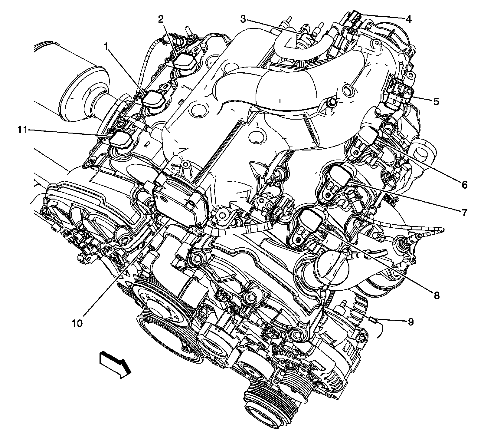
1 - Ignition Coil 3
2 - Ignition Coil 5
3 - Evaporative Emission (EVAP) Canister Purge Solenoid Valve
4 - Throttle Body
5 - Barometric Pressure (BARO) Sensor
6 - Ignition Coil 6
7 - Ignition Coil 4
8 - Ignition Coil 2
9 - Generator Inline Fuse
10 - Intake Manifold Tuning (IMT) Solenoid Valve
11 - Ignition Coil 1
Fuel Injectors
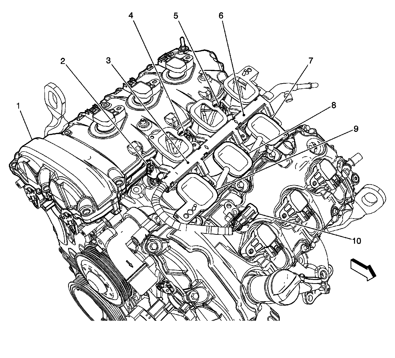
1 - Valve Cover
2 - Fuel Injector 1
3 - J135
4 - Fuel Injector 3
5 - Fuel Injector 5
6 - J137
7 - Fuel Injector 6
8 - Fuel Injector 4
9 - Fuel Injector 2
10 - X101
Engine Components - Front
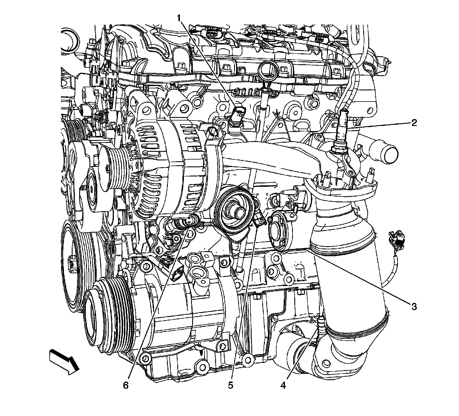
1 - Engine Coolant Temperature (ECT) Sensor
2 - Heated Oxygen Sensor (HO2S) Bank 2 Sensor 1
3 - Starter Motor
4 - Heated Oxygen Sensor (HO2S) Bank 2 Sensor 2
5 - Knock Sensor (KS) 2
6 - Engine Oil Pressure (EOP) Switch
G114
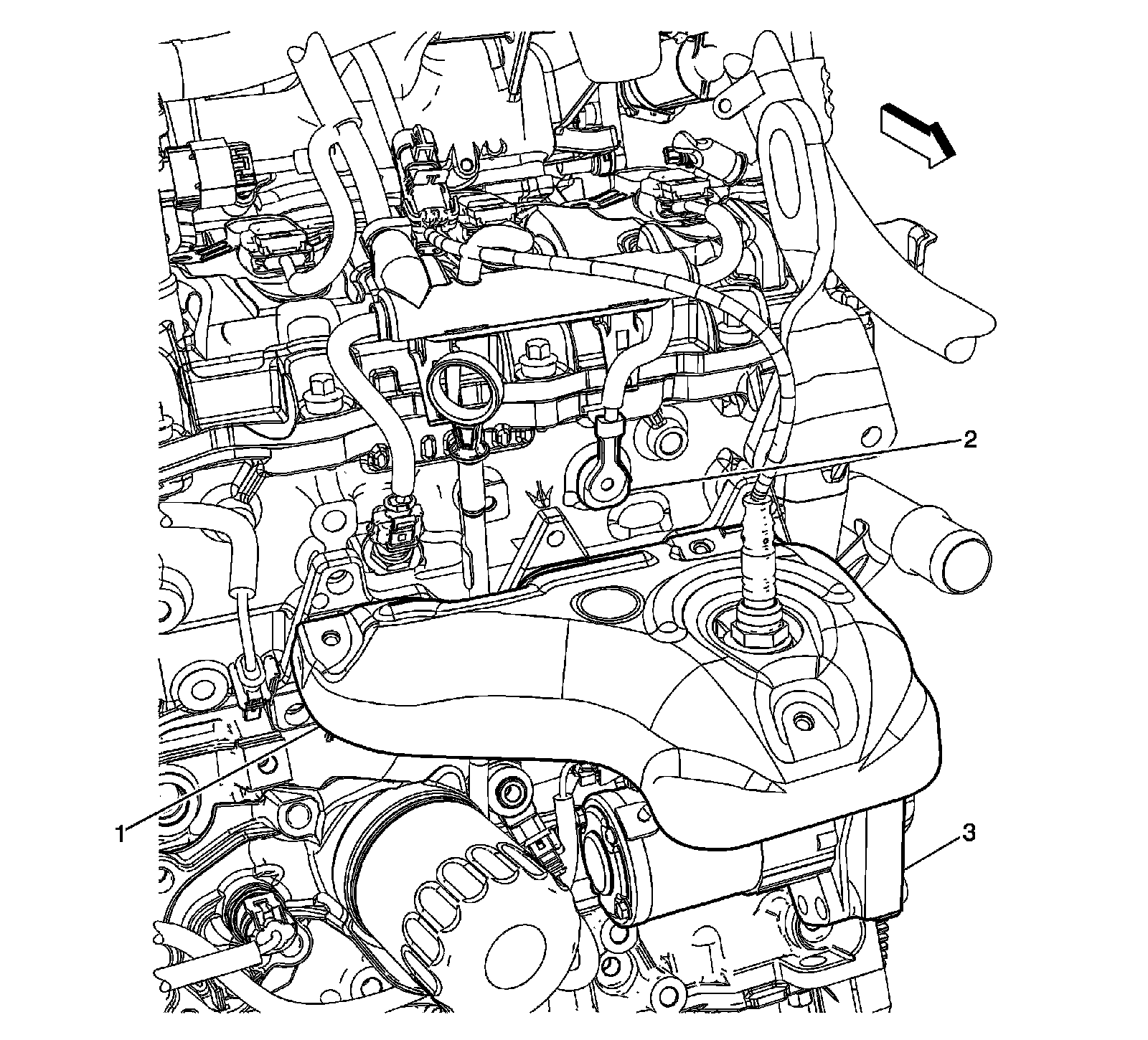
1 - Exhaust Manifold
2 - G114
3 - Starter Motor
Near the A/C Compressor
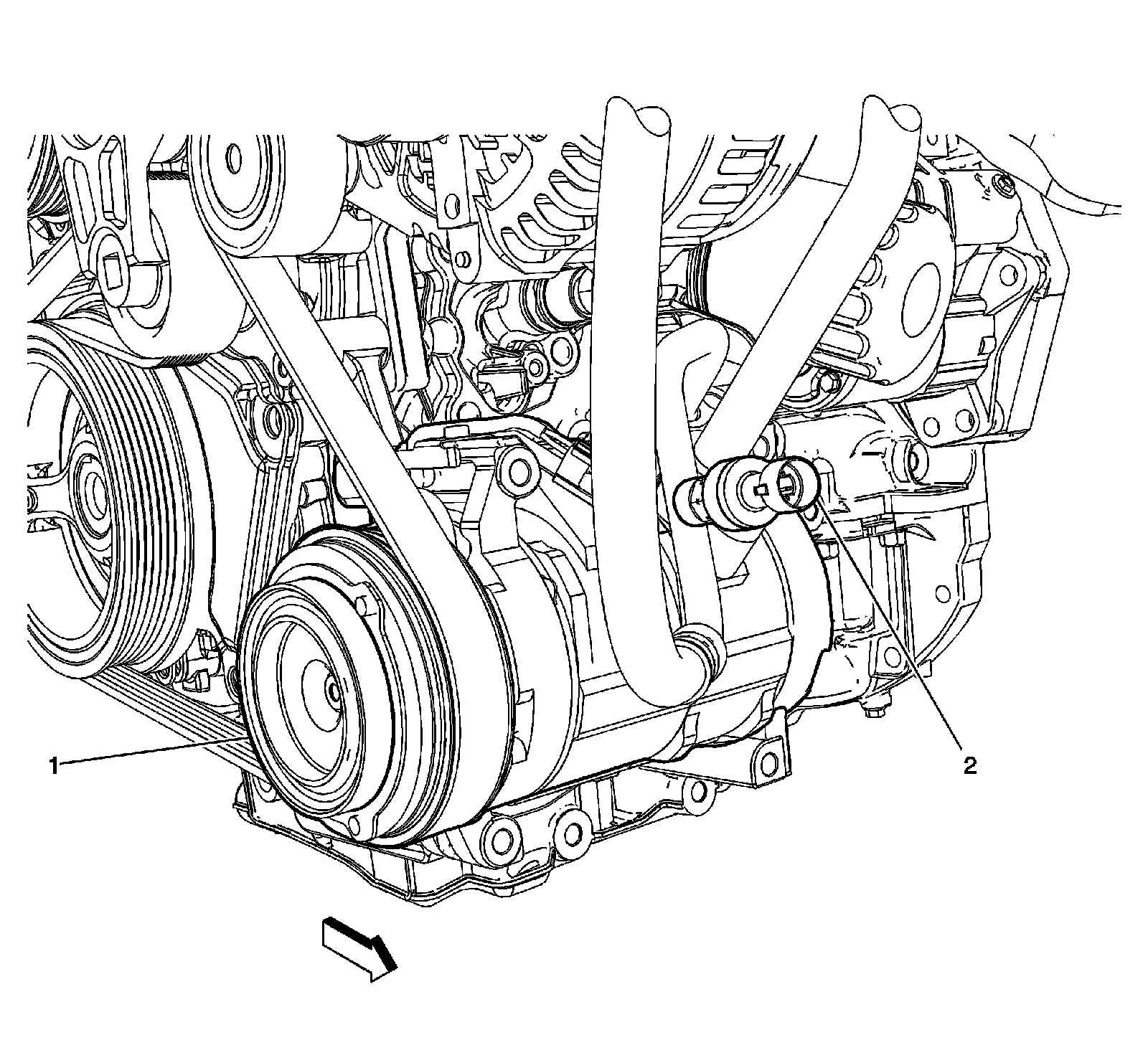
1 - A/C Compressor
2 - A/C Refrigerant Pressure Sensor
Front of the Transmission
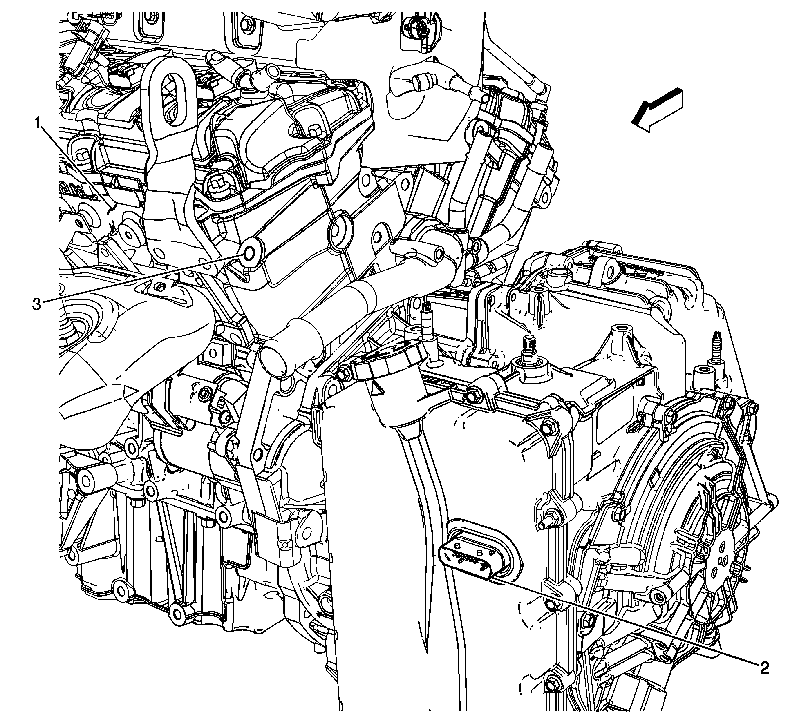
1 - Engine
2 - Automatic Transmission
3 - G113
Automatic Transmission Electronic Components
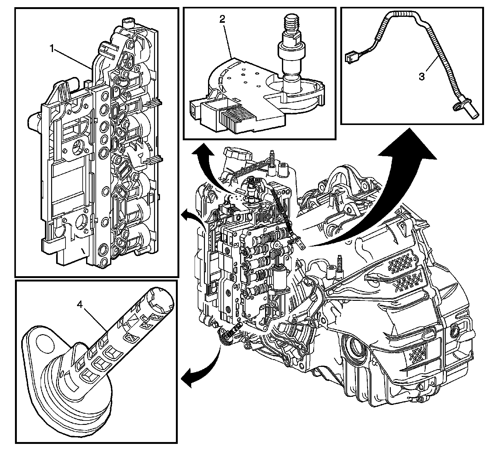
1 - Control Solenoid Valve Assembly
2 - Internal Mode Switch
3 - Output Speed Sensor (OSS)
4 - Input Speed Sensor (ISS)
Near the Water Pump
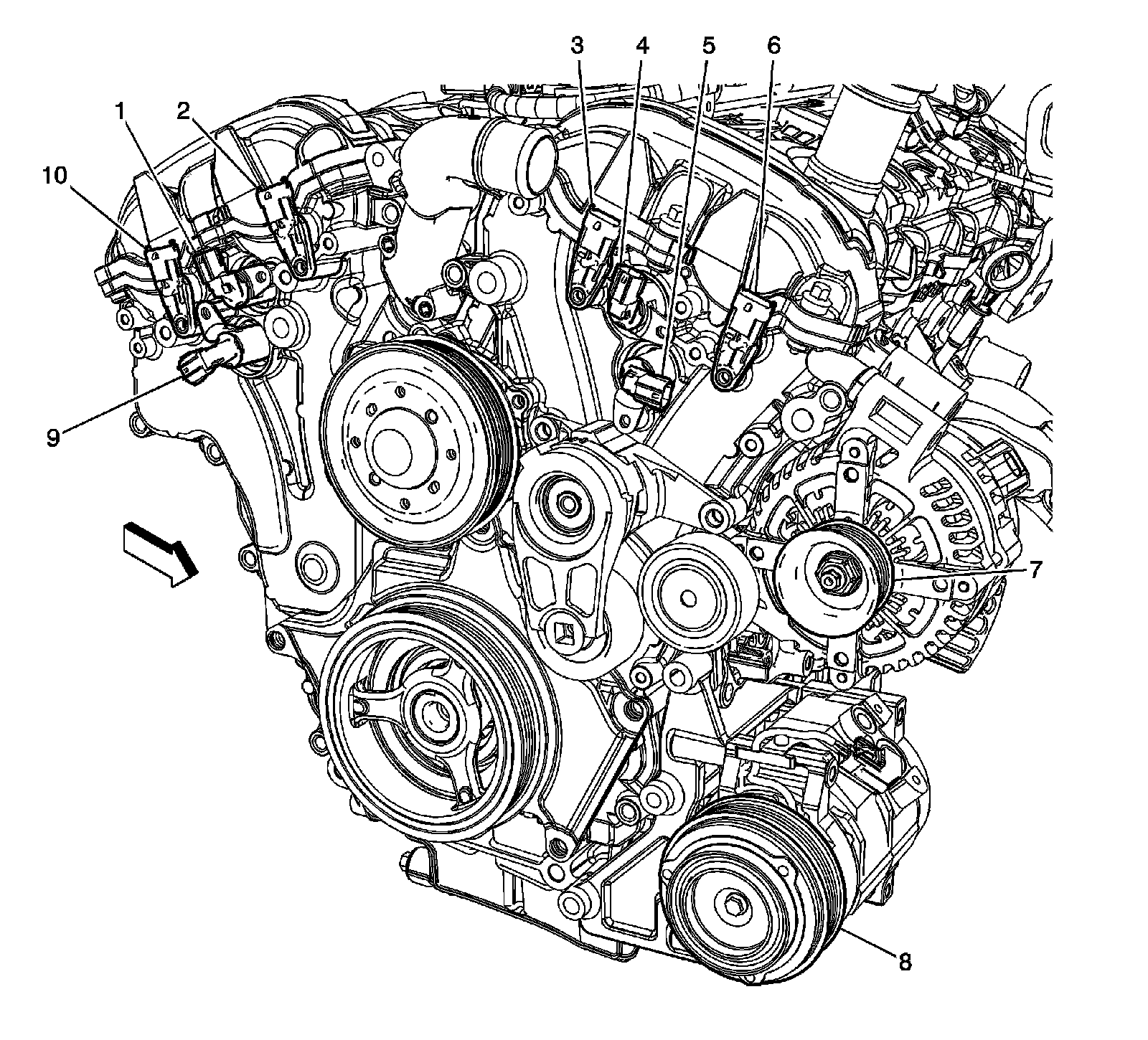
1 - Camshaft Position (CMP) Actuator Solenoid - Intake Bank 1
2 - Camshaft Position (CMP) Sensor - Intake Bank 1
3 - Camshaft Position (CMP) Sensor - Intake Bank 2
4 - Camshaft Position (CMP) Actuator Solenoid - Intake Bank 2
5 - Camshaft Position (CMP) Actuator Solenoid - Exhaust Bank 2
6 - Camshaft Position (CMP) Sensor - Exhaust Bank 2
7 - Generator
8 - A/C Compressor Clutch
9 - Camshaft Position (CMP) Actuator Solenoid - Exhaust Bank 1
10 - Camshaft Position (CMP) Sensor - Exhaust Bank 1
G110 and G112
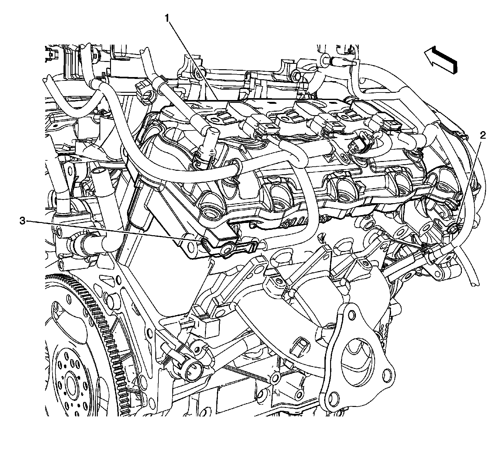
1 - Valve Cover
2 - G110
3 - G112
Engine Components - Rear
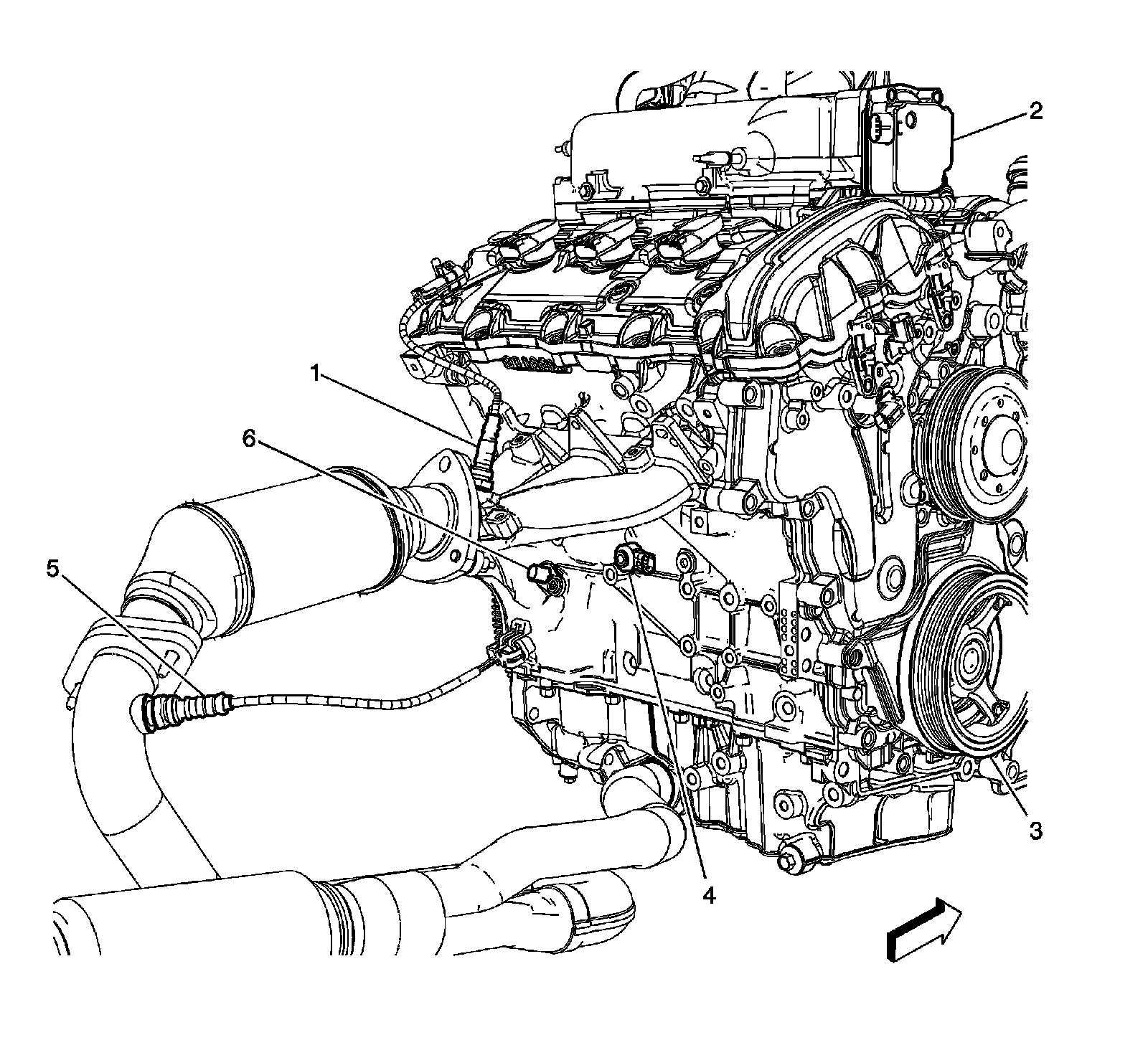
1 - Heated Oxygen Sensor (HO2S) Bank 1 Sensor 1
2 - Intake Manifold Tuning (IMT) Solenoid Valve
3 - Crankshaft Pulley
4 - Knock Sensor (KS) 1
5 - Heated Oxygen Sensor (HO2S) Bank 1 Sensor 2
6 - Crankshaft Position (CKP) Sensor
Left Front of Engine Compartment
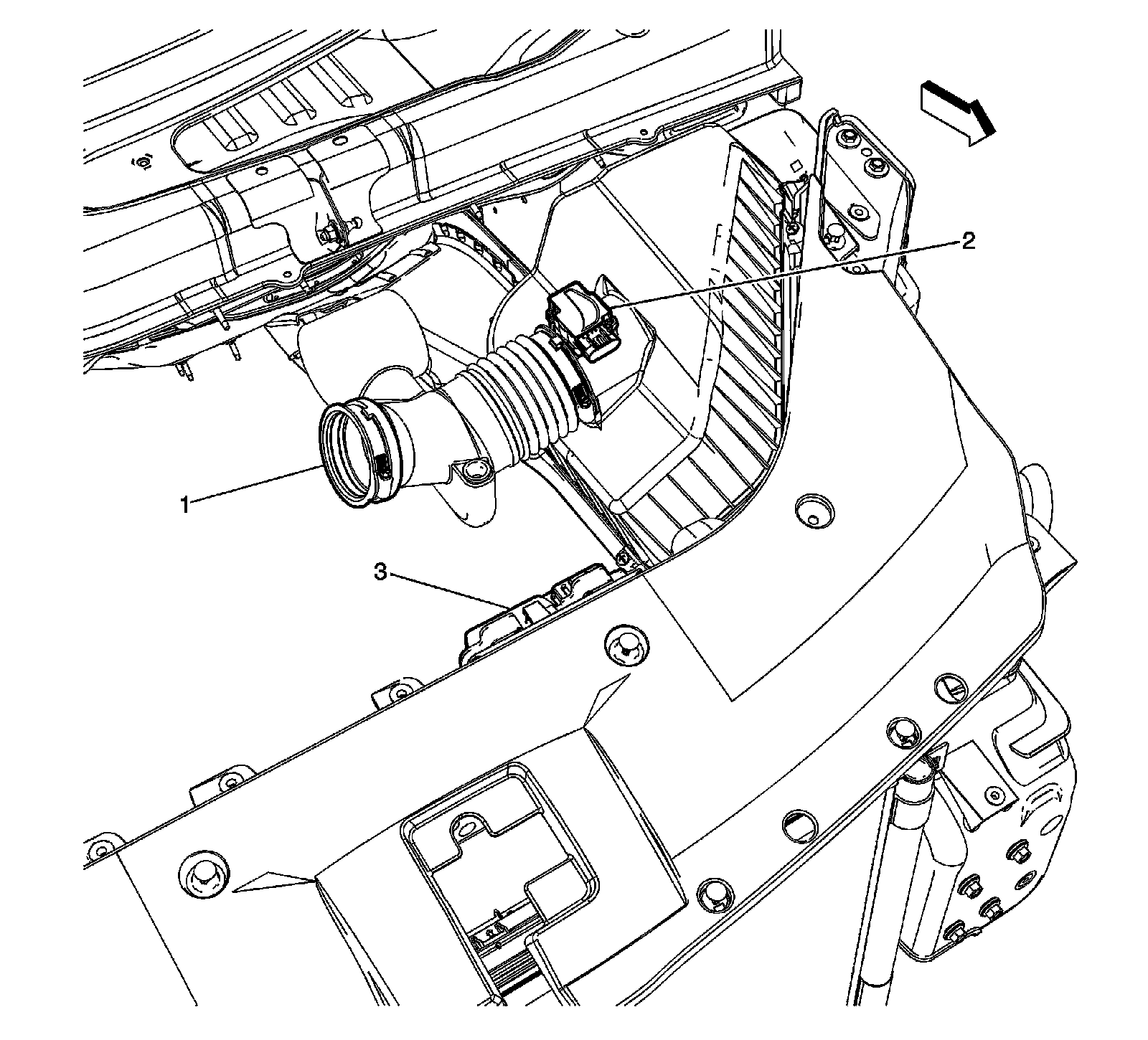
1 - Air Intake
2 - Mass Air Flow (MAF)/Intake Air Temperature (IAT) Sensor
3 - Engine Control Module (ECM)
Factory Service Tools
Use the Manual With the Right Hardware
Pair factory procedures with proven DIY tools so the instructions are easier to execute.
Disclosure: Verified tool recommendations may earn an affiliate commission at no cost to you.
When to See a Mechanic
Stop DIY work and contact a certified mechanic immediately if any of the following apply:
- • You smell fuel, burning insulation, or see smoke.
- • Brakes feel soft, pull hard to one side, or make grinding noises.
- • The engine overheats, stalls repeatedly, or misfires under load.
- • You are missing required tools, torque specs, or safe lifting equipment.
- • You are not confident in the next step or safety outcome.