
Safety Warning
DIY auto repair can cause serious injury, fire, or vehicle damage. These guides are for informational purposes only. Always follow OEM torque specs, wear PPE, and consult a certified mechanic if you are unsure. You are solely responsible for your safety.
2008 GMC Acadia AWD V6-3.6LFACTORY OEM SERVICE PROCEDURE
Instrument Panel/Center Console Component Views
Instrument Panel/Center Console Component Views
Near the Steering Column
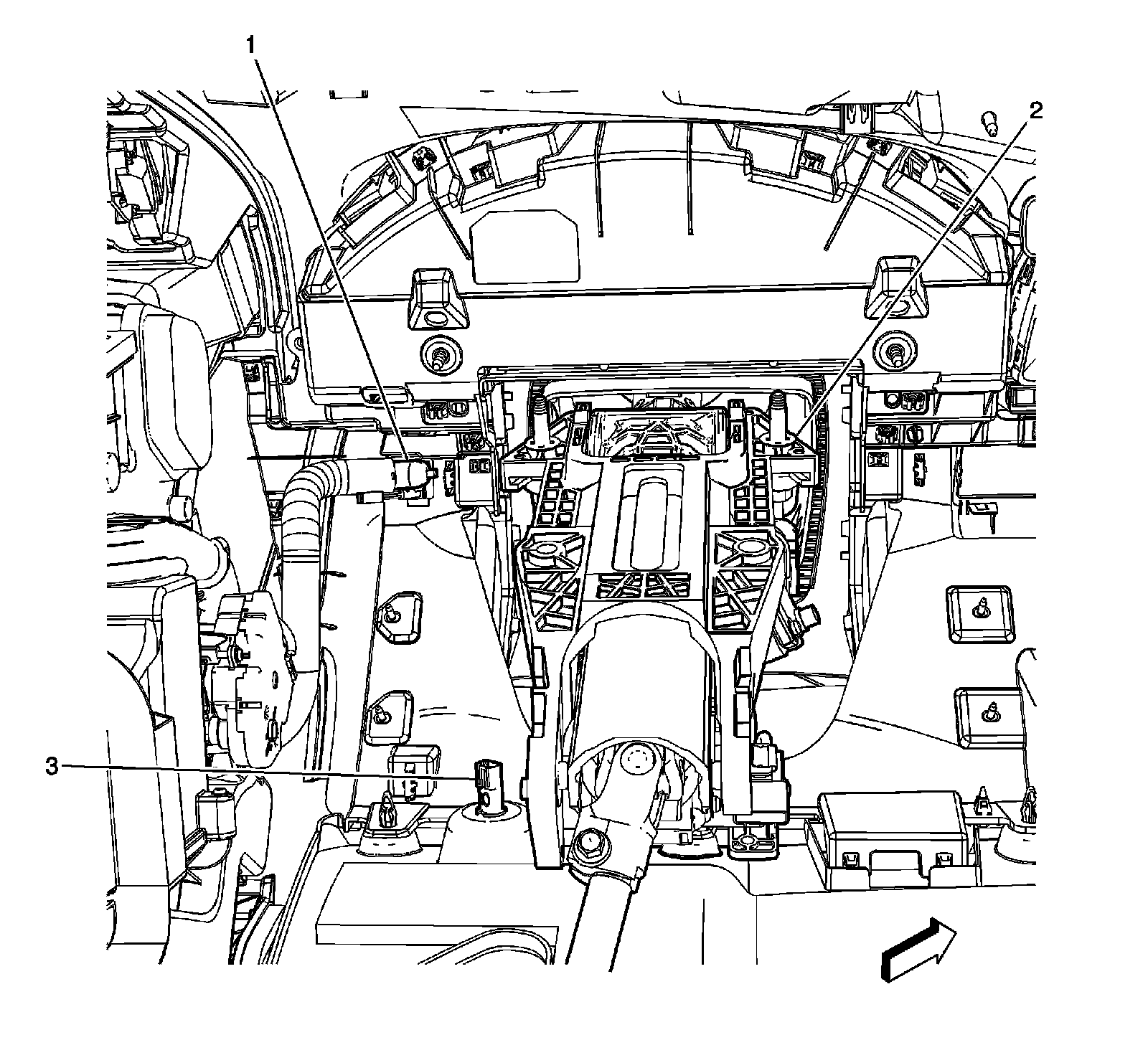
1 - Inside Air Temperature Sensor
2 - Steering Column
3 - Courtesy Lamp - Left Footwell
Interior HVAC Module - Front (CJ2)
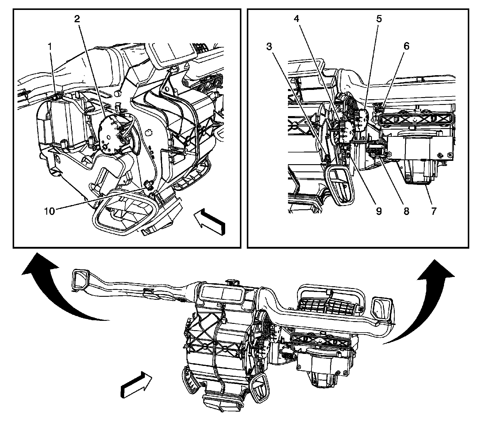
1 - Air Temperature Sensor - Upper Left
2 - Air Temperature Actuator - Left
3 - Air Temperature Sensor - Lower Right
4 - Air Temperature Actuator - Right
5 - Mode Actuator
6 - Air Temperature Sensor - Upper Right
7 - Blower Motor
8 - Blower Motor Control Module
9 - Evaporator Temperature Sensor
10 - Air Temperature Sensor - Lower Left
Front HVAC Module (C67)
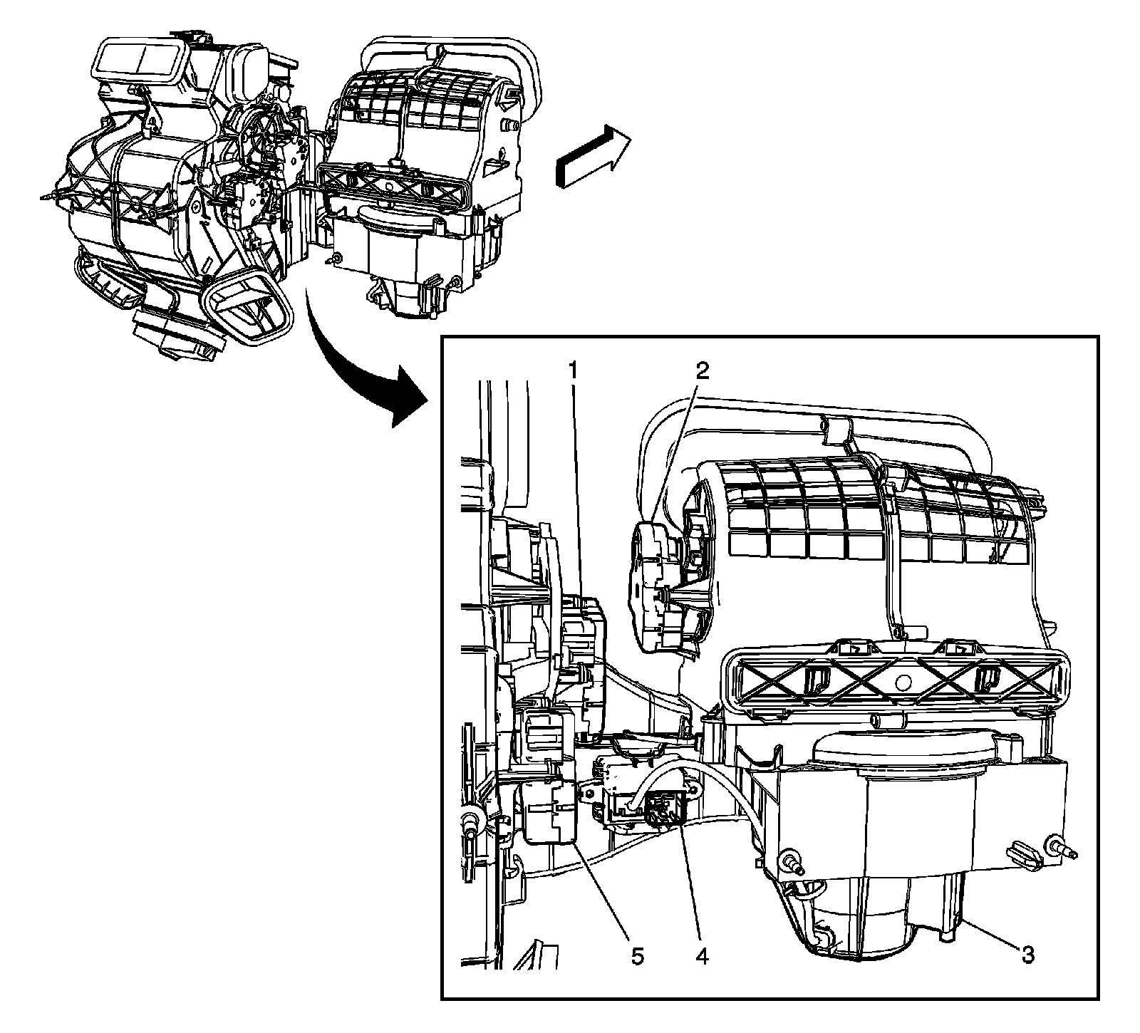
1 - Mode Actuator
2 - Recirculation Actuator
3 - Blower Motor
4 - Blower Motor Control Module
5 - Air Temperature Actuator
6 - Evaporator Temperature Sensor
Behind the I/P Compartment
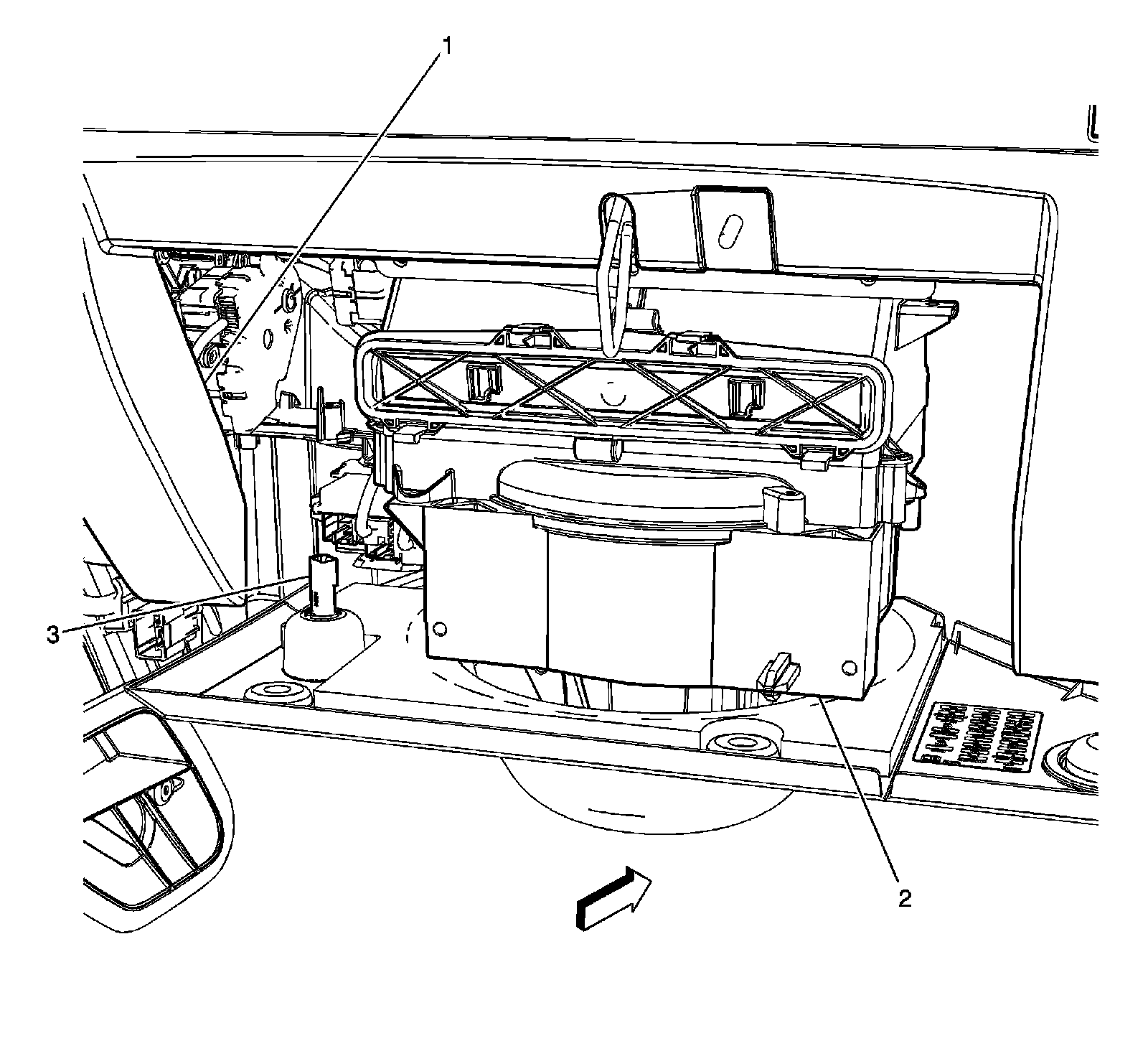
1 - I/P Trim
2 - HVAC Module Assembly
3 - Courtesy Lamp - Right Footwell
Behind the I/P Compartment
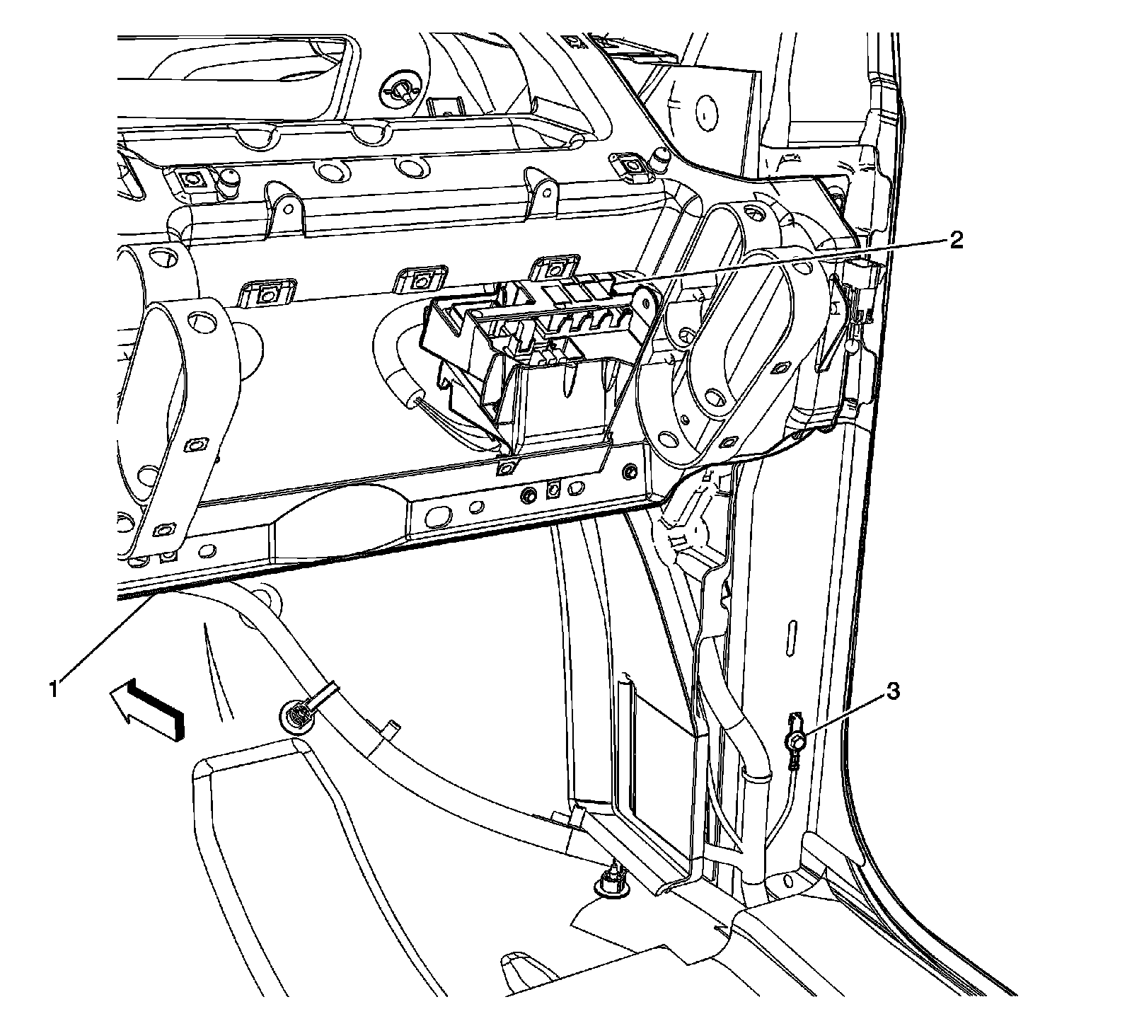
1 - I/P Structure
2 - Fuse Block - I/P
3 - G300
Above the Instrument Cluster (UV6)
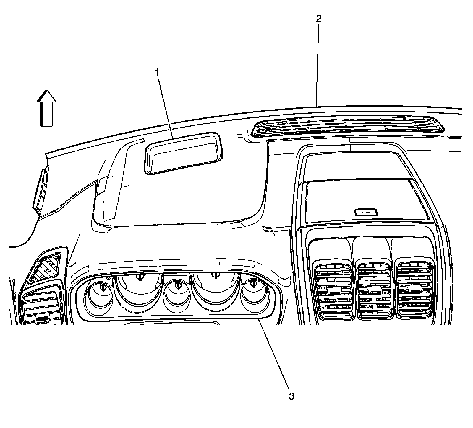
1 - Head Up Display (HUD)
2 - I/P Trim
3 - Instrument Panel Cluster (IPC)
Near the Passenger A Pillar
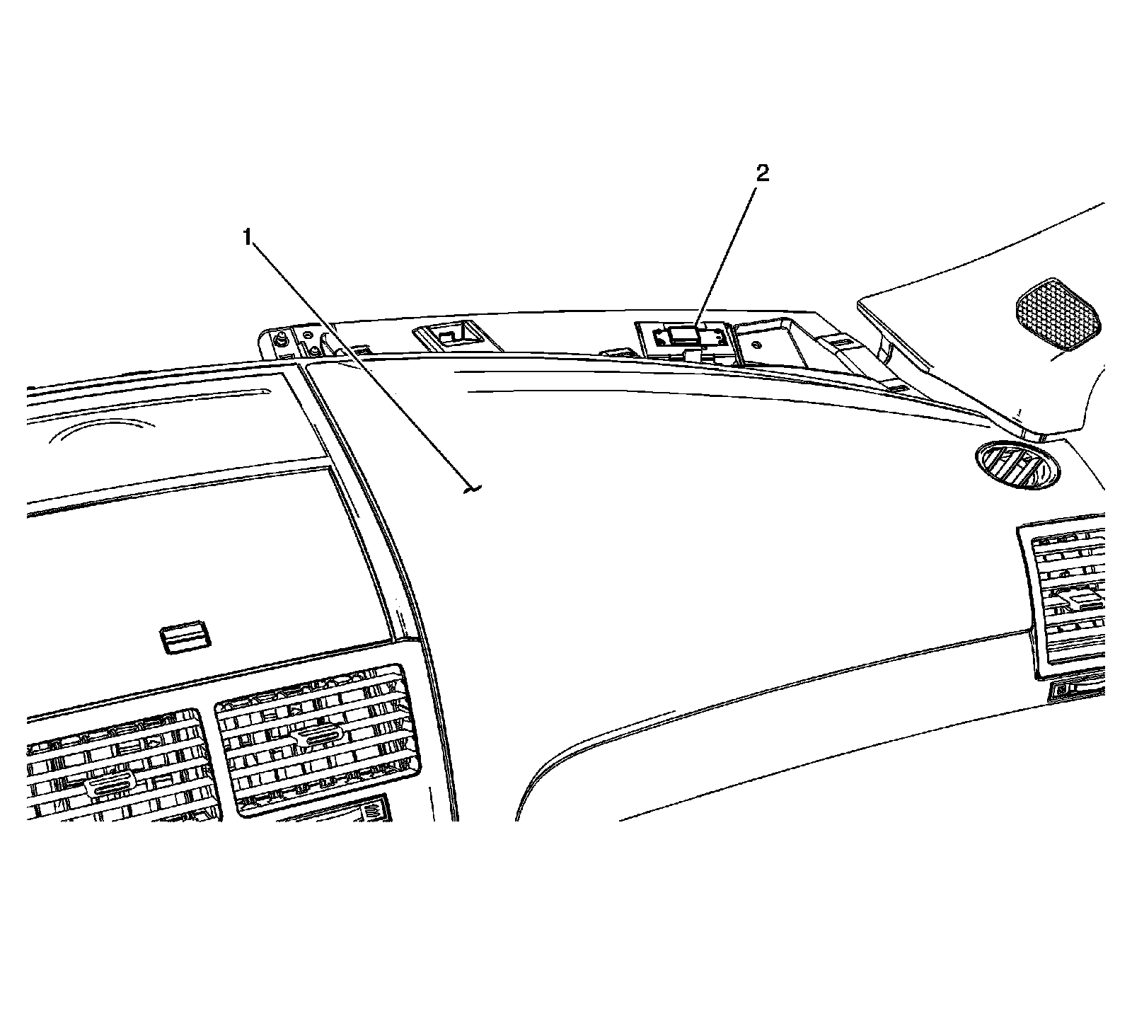
1 - I/P Trim
2 - Navigation Antenna (U3R/UZR)
Analog Clock (W49)
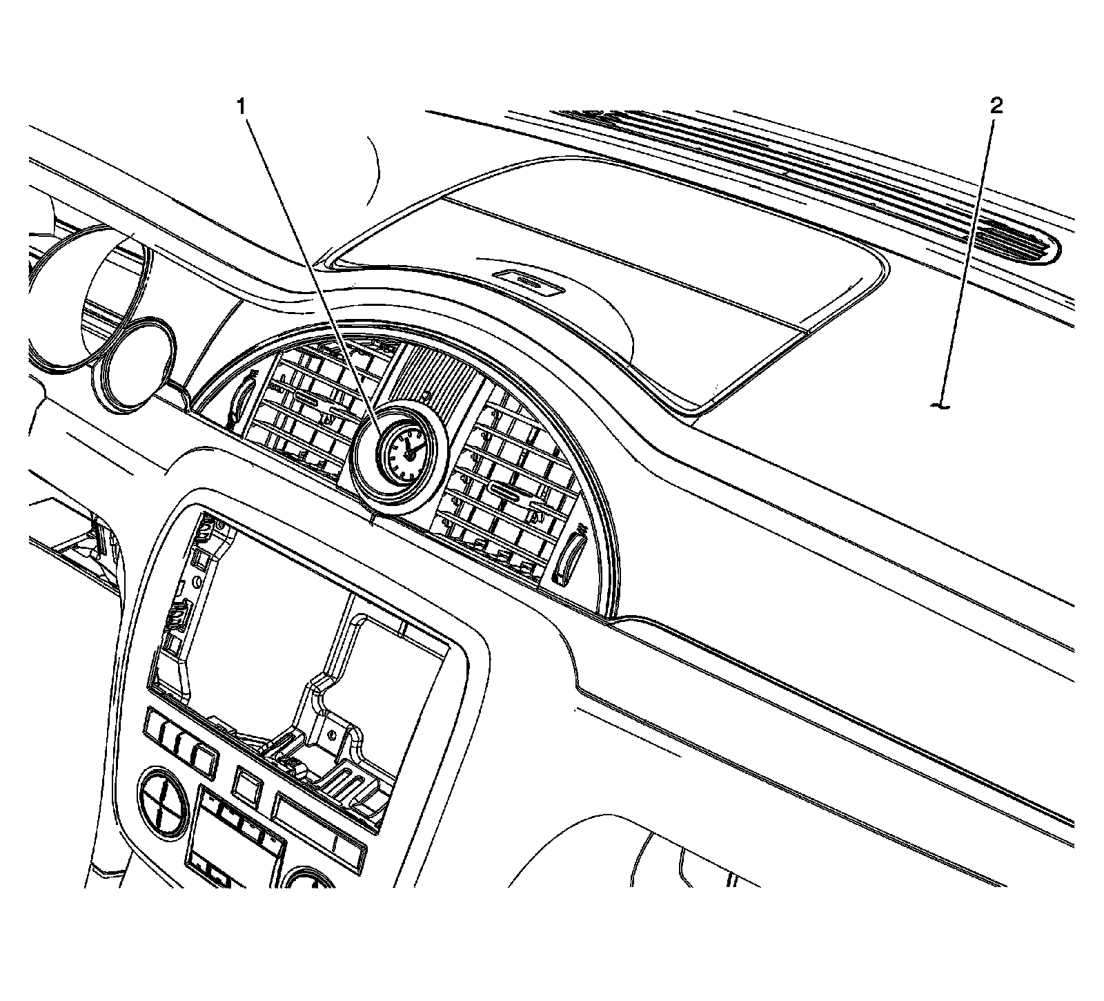
1 - Analog Clock
2 - I/P Trim
Front Air Bags
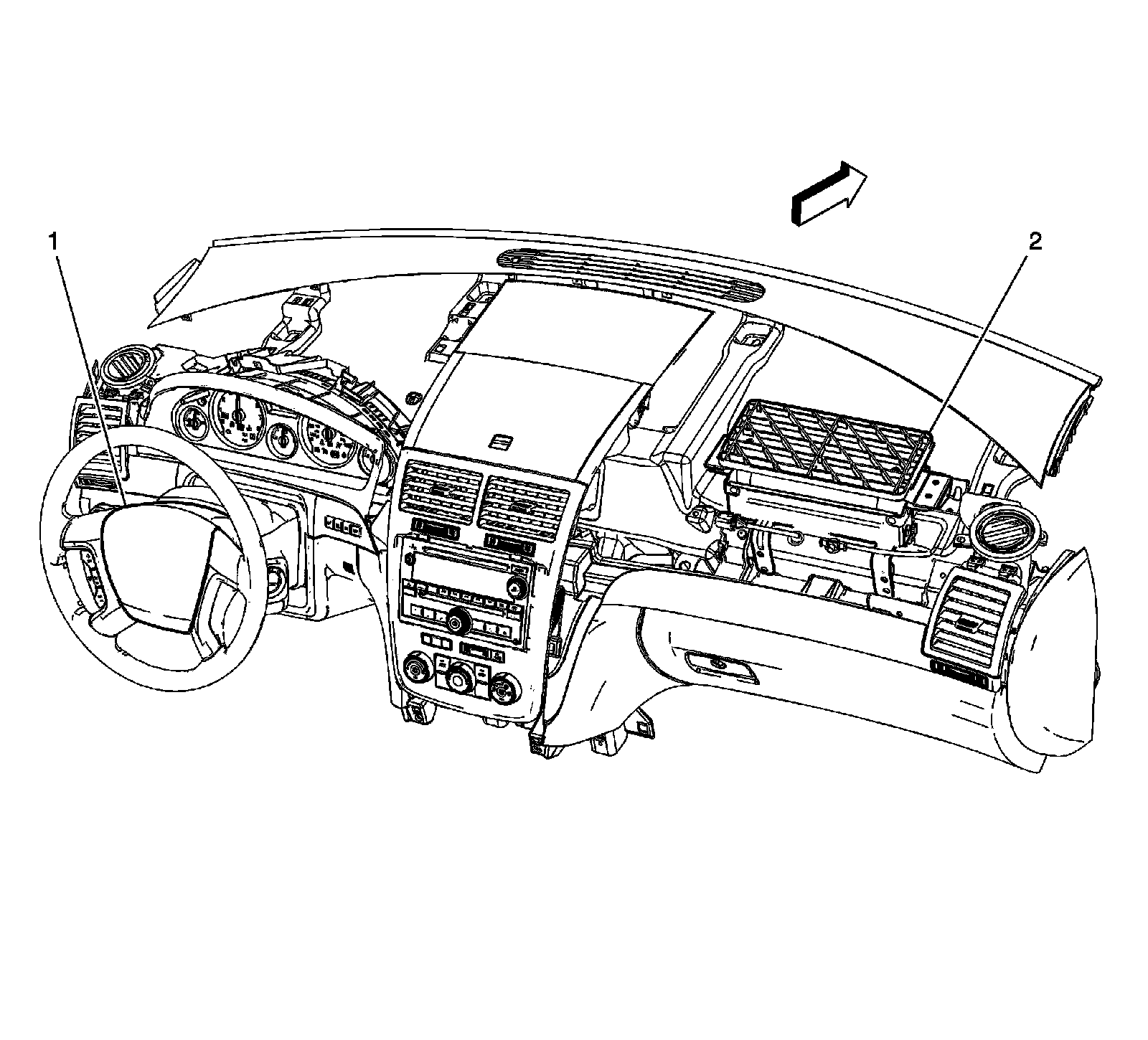
1 - Inflatable Restraint Steering Wheel Module
2 - Inflatable Restraint I/P Module
I/P Compartment Components
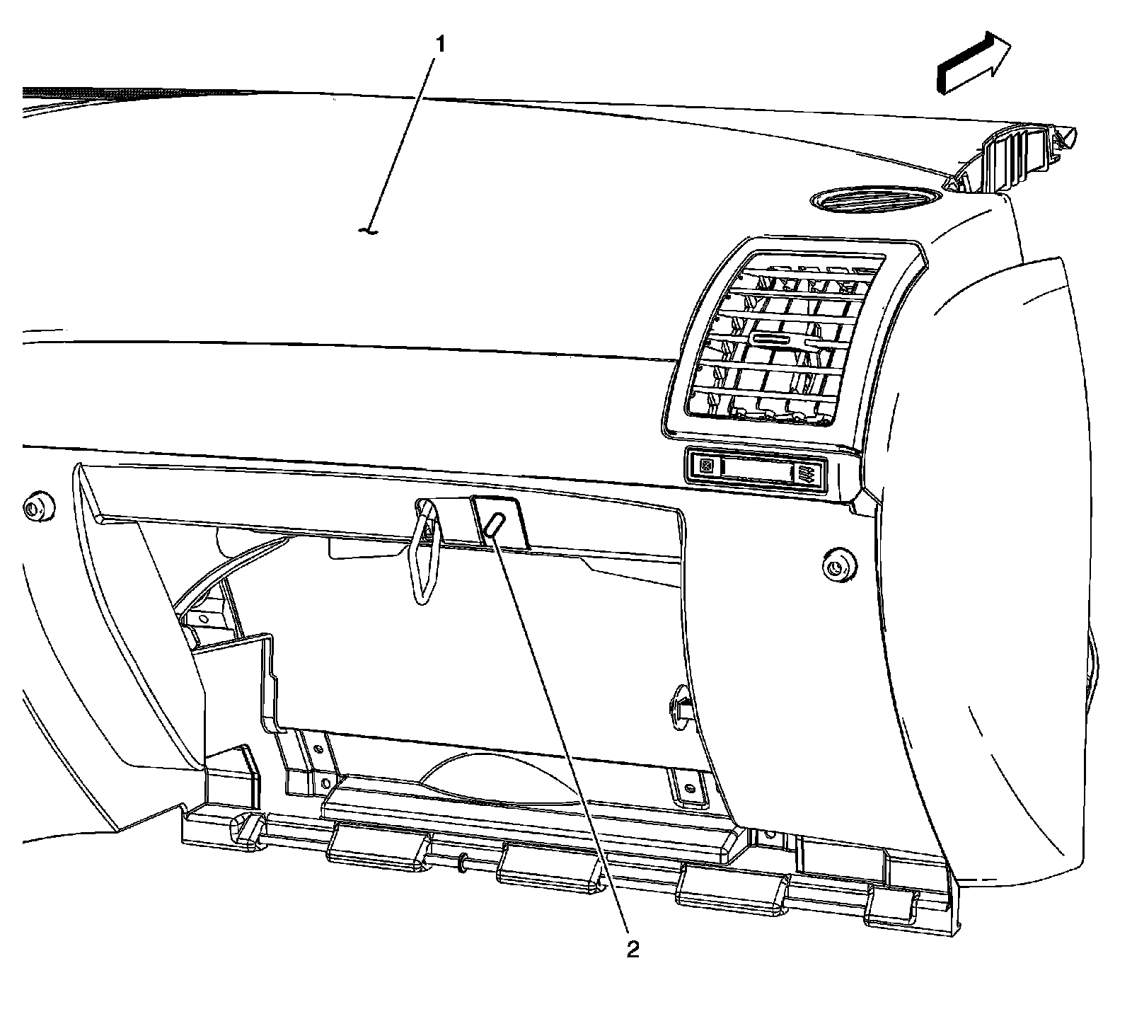
1 - I/P Trim
2 - I/P Compartment Lamp
I/P Components
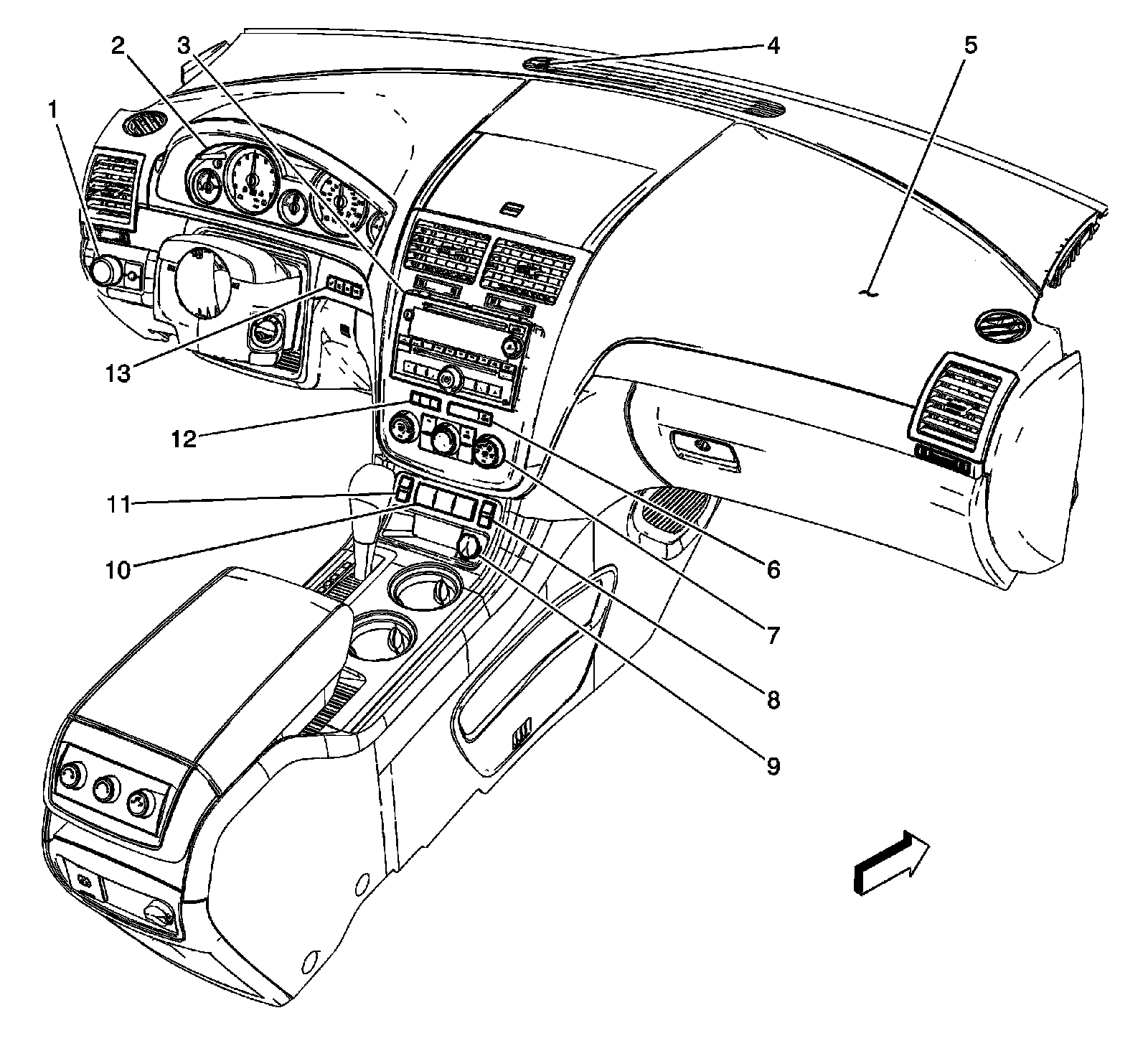
1 - Headlamp Switch
2 - Instrument Panel Cluster (IPC)
3 - Radio
4 - Sunload Sensor (CJ2) / Ambient Light Sensor (C67)
5 - I/P Trim
6 - Inflatable Restraint PASSENGER AIR BAG ON/OFF Indicator
7 - HVAC Control Module
8 - Heated Seat Switch - Passenger (KA1)
9 - Auxiliary Power Outlet - I/P
10 - I/P Switch Assembly
11 - Heated Seat Switch - Driver (KA1)
12 - Hazard Switch, and Driver Information Center (DIC) Switch (W49/Z88)
13 - Head Up Display (HUD) Switch (UV6+WDA)
14 - Driver Information Center (DIC) Switch (UH9+WDA)/Head Up Display (HUD) Switch (UV6+W49/Z88)
Below the Center I/P Trim
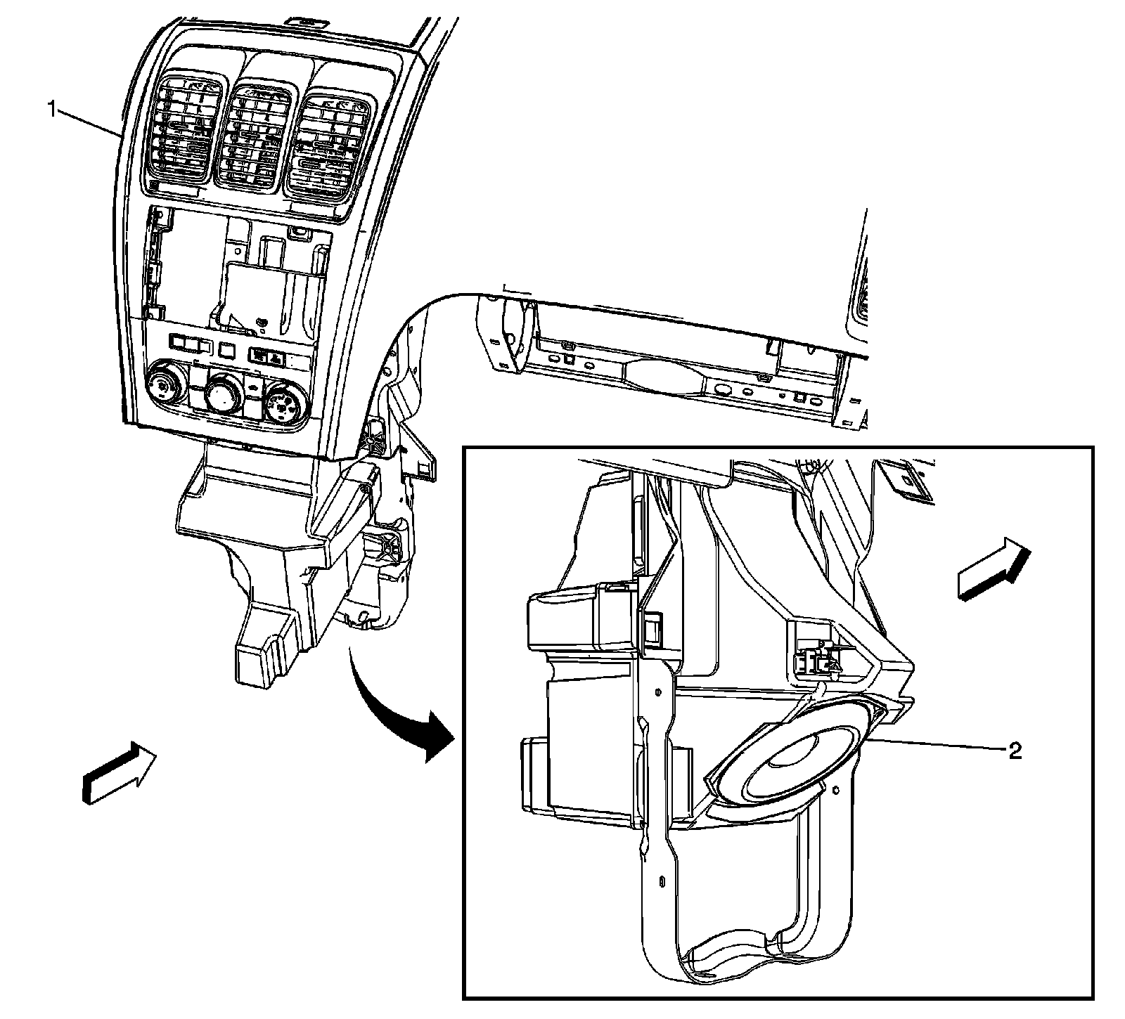
1 - I/P Trim
2 - Speaker - Subwoofer (UQA/UQG/UQS)
Steering Column Components
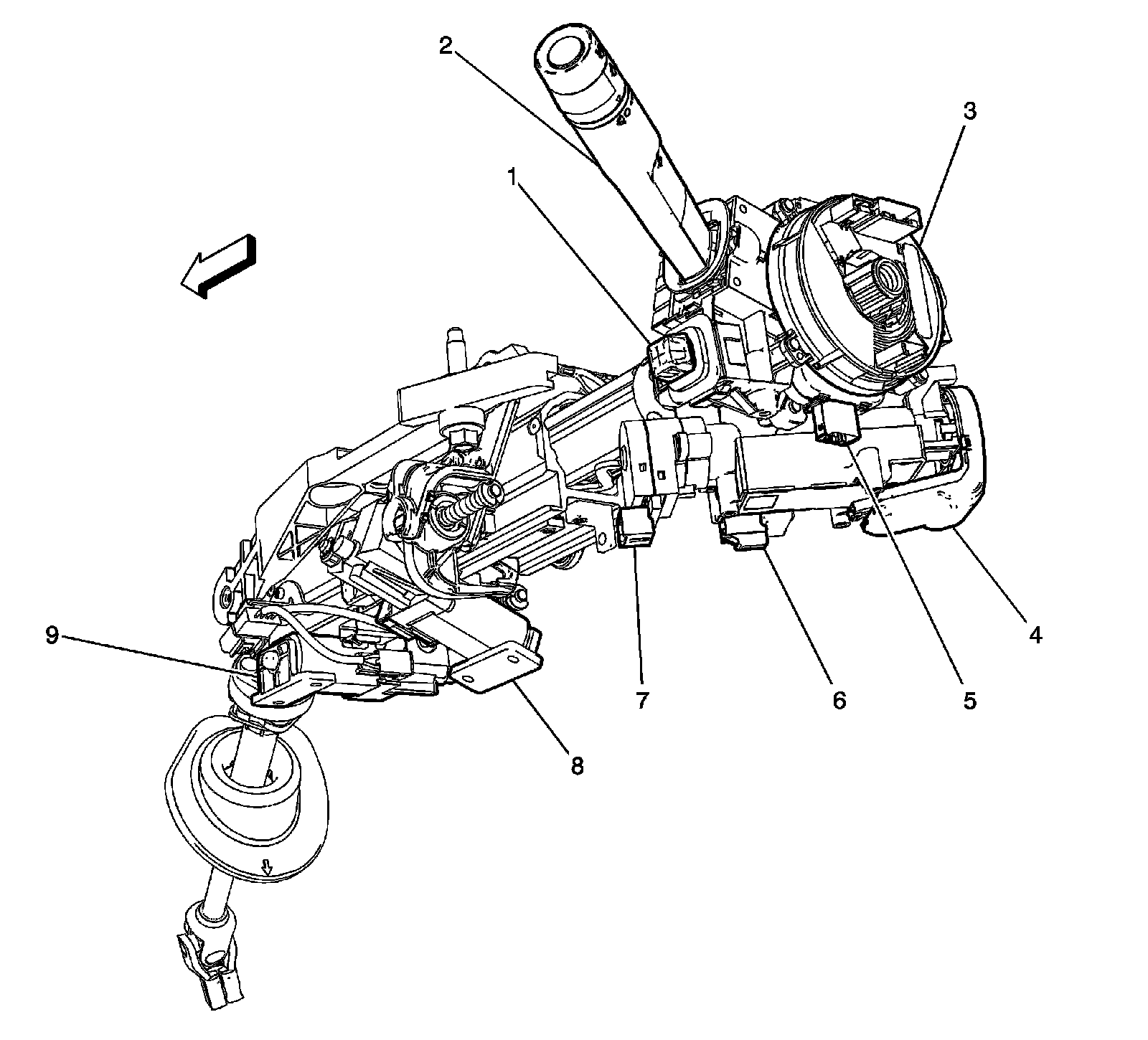
1 - Tilt/Telescope Switch (N38)
2 - Turn Signal/Multifunction Switch
3 - Inflatable Restraint Steering Wheel Module Coil
4 - Theft Deterrent Control Module
5 - Steering Wheel Speed Position Sensor
6 - Ignition Lock Cylinder Control Actuator
7 - Ignition Switch
8 - Tilt Motor (N38)
9 - Telescope Actuator (N38)
Steering Wheel Components
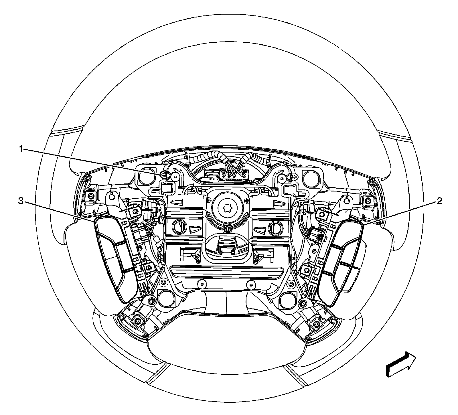
1 - Horn Switch
2 - Steering Wheel Control Switch Assembly - Right (UK3)
3 - Steering Wheel Control Switch Assembly - Left
Below the Driver Side I/P
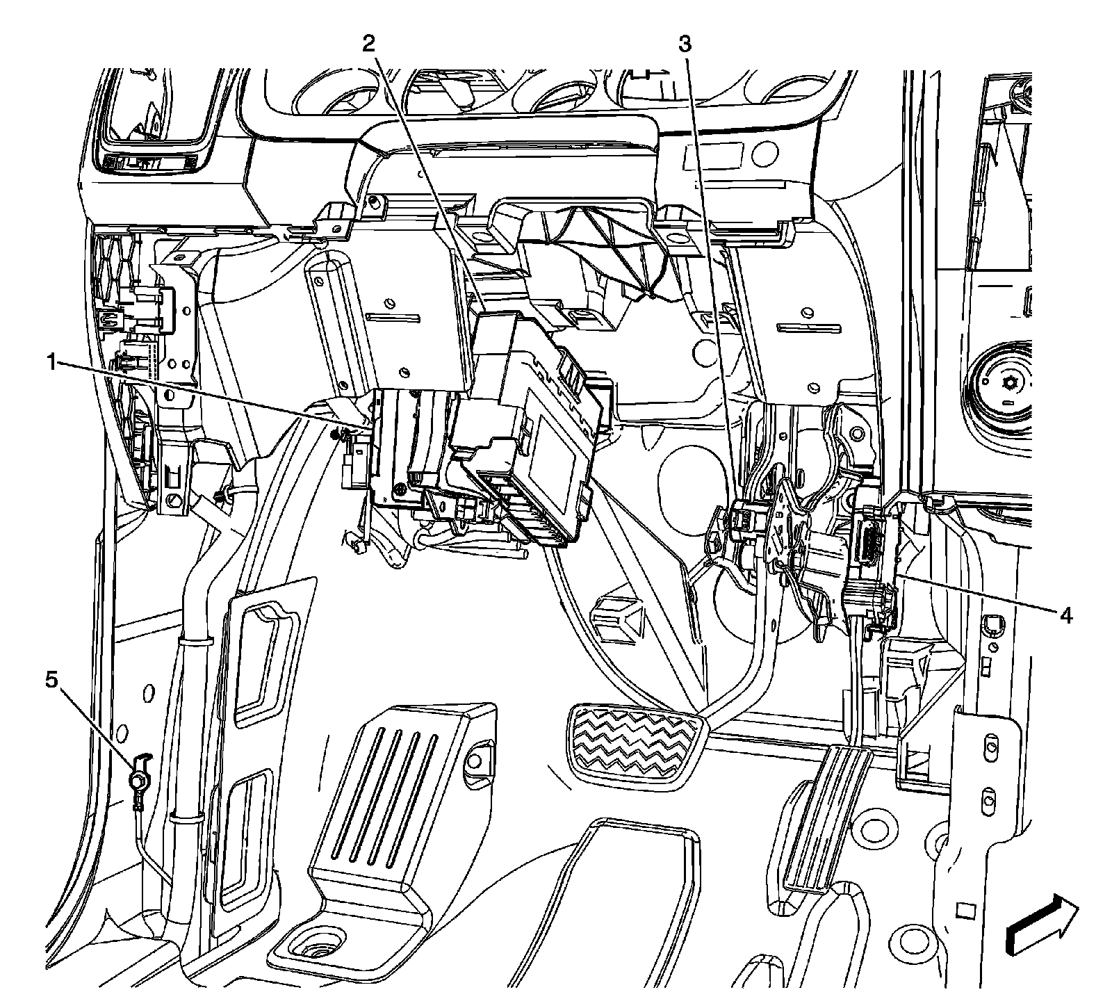
1 - Audio Amplifier (UQA/UQG/UQS)
2 - Body Control Module (BCM)
3 - Brake Pedal Position Sensor
4 - Accelerator Pedal Position (APP) Sensor
5 - G301
6 - Park Brake Switch
Data Link Connector

1 - Data Link Connector (DLC)
2 - Pedal Assembly
3 - Floor Panel
I/P Speakers
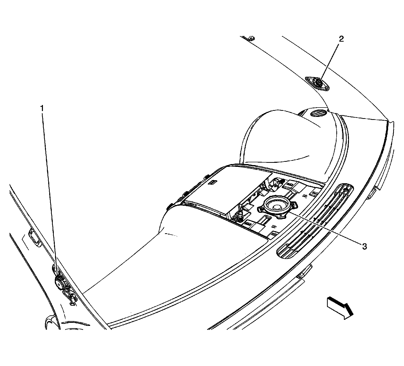
1 - Speaker - Right Front Tweeter
2 - Speaker - Left Front Tweeter
3 - Speaker - Center (UQA/UQG/UQS)
In the Front Floor Console
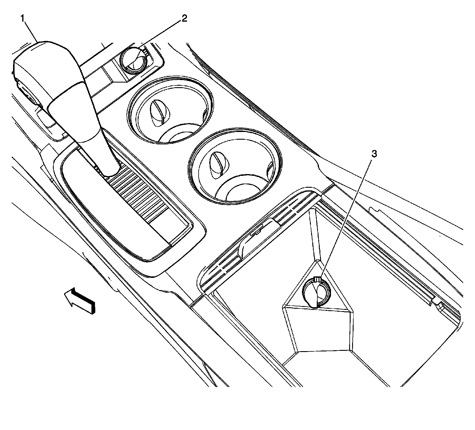
1 - Automatic Transmission Shift Lever
2 - Auxiliary Power Outlet - I/P
3 - Auxiliary Power Outlet - Console Compartment
Shifter Assembly
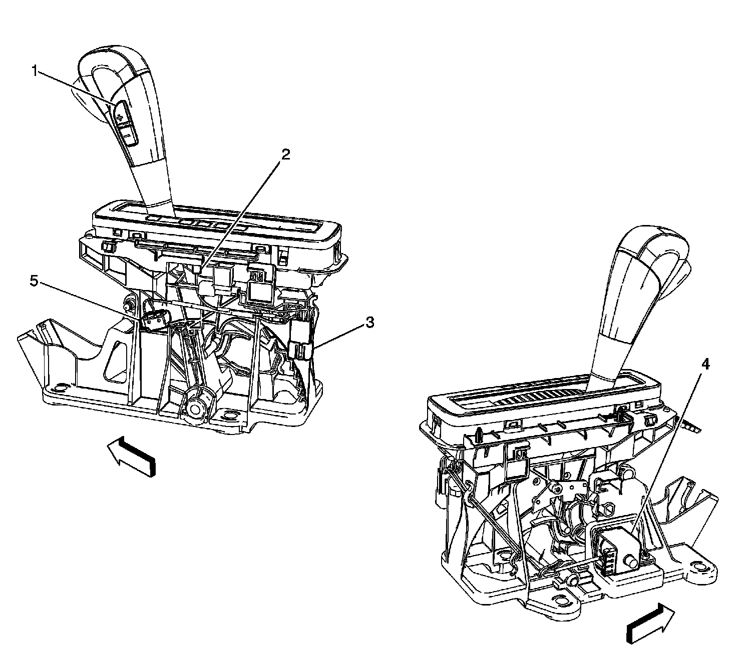
1 - Tap Up/Tap Down Switch
2 - PRNDL Lamp
3 - X341
4 - A/T Shift Lock Control Solenoid
5 - Ignition Lock Switch
Console Components
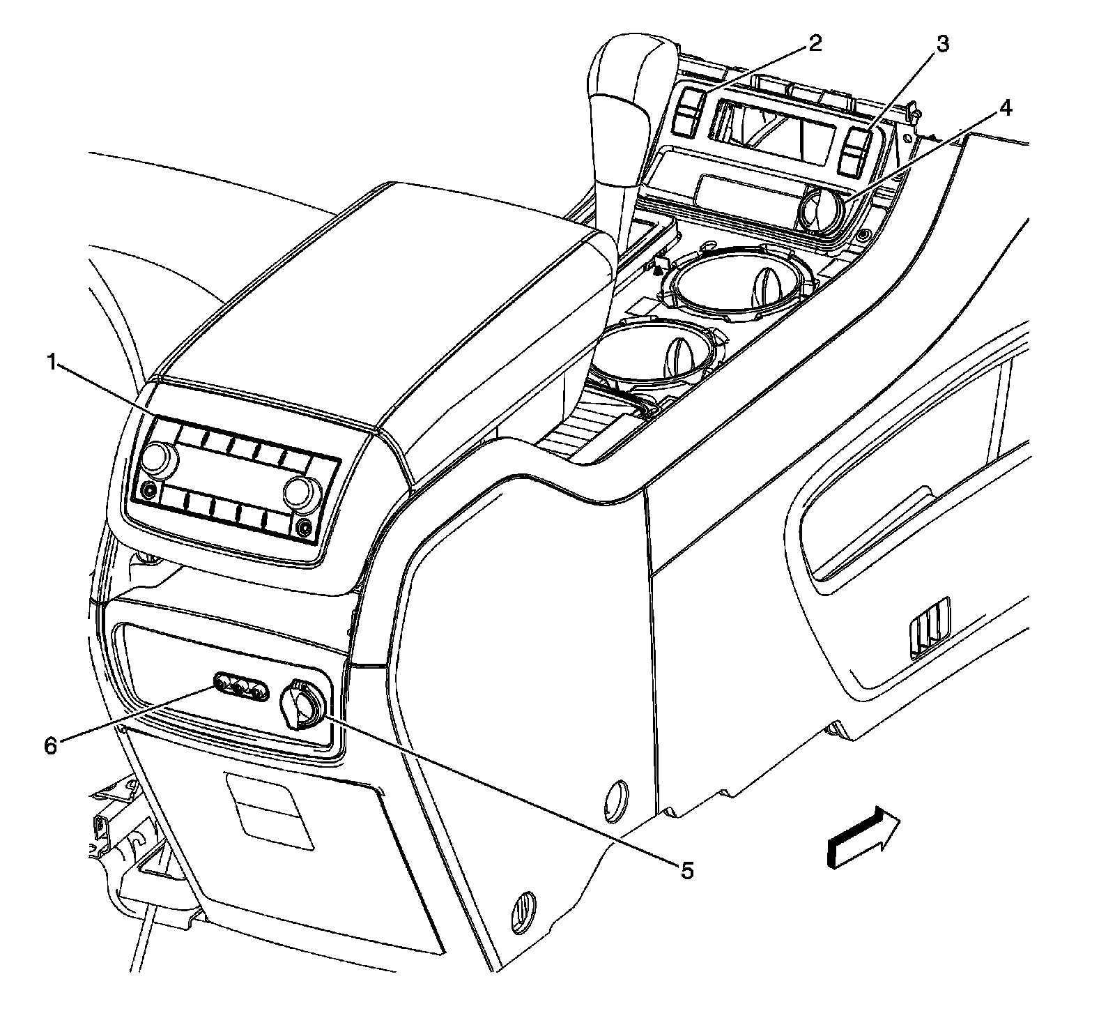
1 - Rear Audio/HVAC Module (UK6)/HVAC Control Assembly - Auxiliary (-UK6)
2 - Heated Seat Switch - Driver (KA1)
3 - Heated Seat Switch - Passenger (KA1)
4 - Auxiliary Power Outlet - I/P
5 - Auxiliary Power Outlet - Console Rear
6 - Audio/Video Adapter (U42)
Rear of the Floor Console
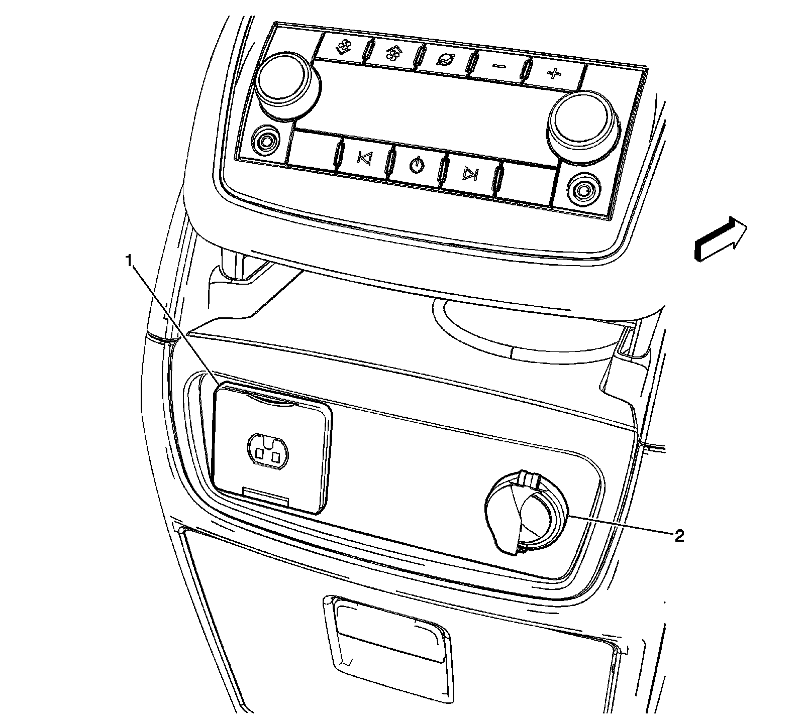
1 - Auxiliary Power Outlet - 115VAC (KV1)
2 - Auxiliary Power Outlet - Console Rear
Factory Service Tools
Use the Manual With the Right Hardware
Pair factory procedures with proven DIY tools so the instructions are easier to execute.
Disclosure: Verified tool recommendations may earn an affiliate commission at no cost to you.
When to See a Mechanic
Stop DIY work and contact a certified mechanic immediately if any of the following apply:
- • You smell fuel, burning insulation, or see smoke.
- • Brakes feel soft, pull hard to one side, or make grinding noises.
- • The engine overheats, stalls repeatedly, or misfires under load.
- • You are missing required tools, torque specs, or safe lifting equipment.
- • You are not confident in the next step or safety outcome.