
Safety Warning
DIY auto repair can cause serious injury, fire, or vehicle damage. These guides are for informational purposes only. Always follow OEM torque specs, wear PPE, and consult a certified mechanic if you are unsure. You are solely responsible for your safety.
2008 Freightliner Sprinter 2500 V6-3.0L DSL TurboFACTORY OEM SERVICE PROCEDURE
Engine Torque Specifications
TORQUE
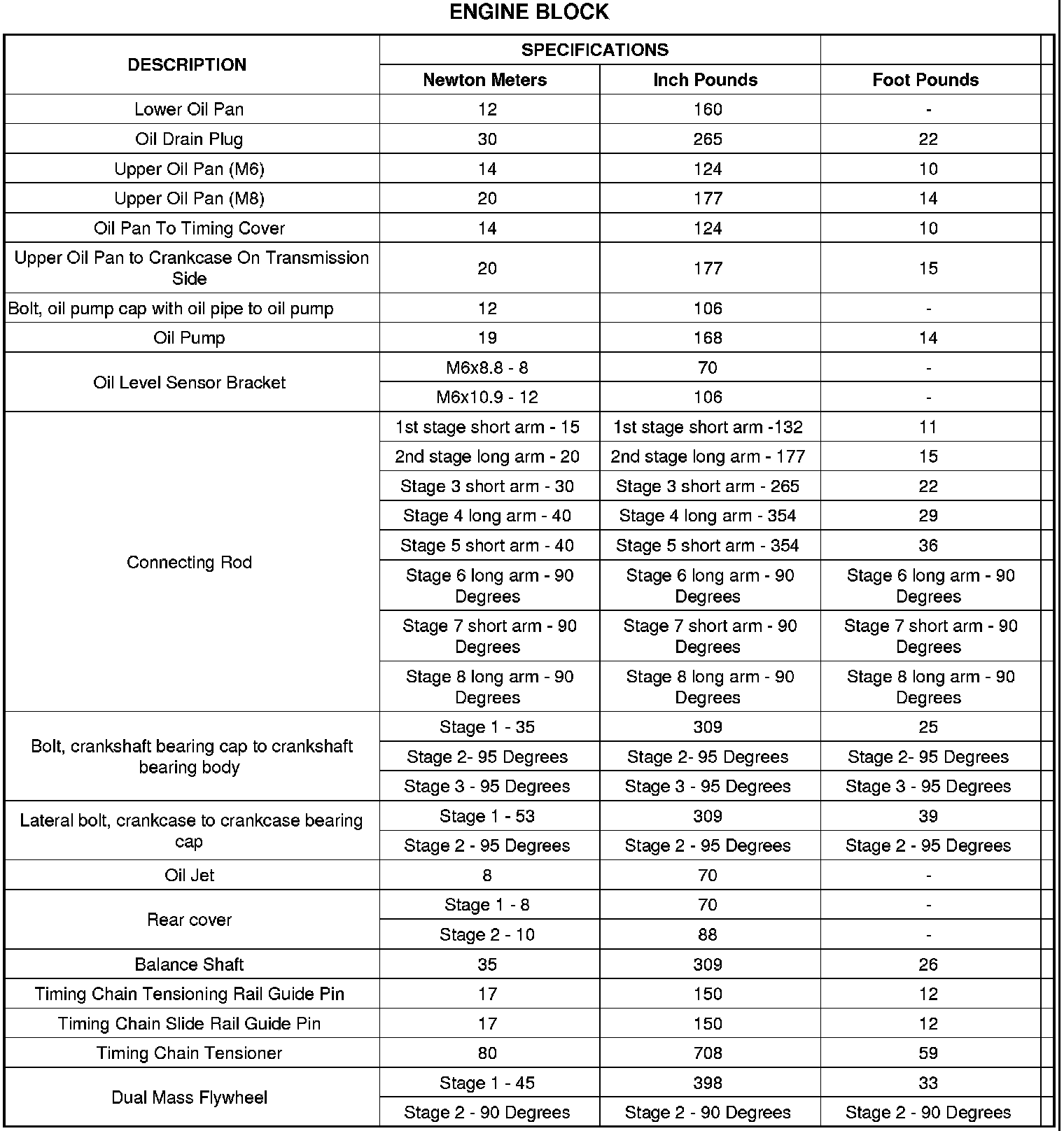

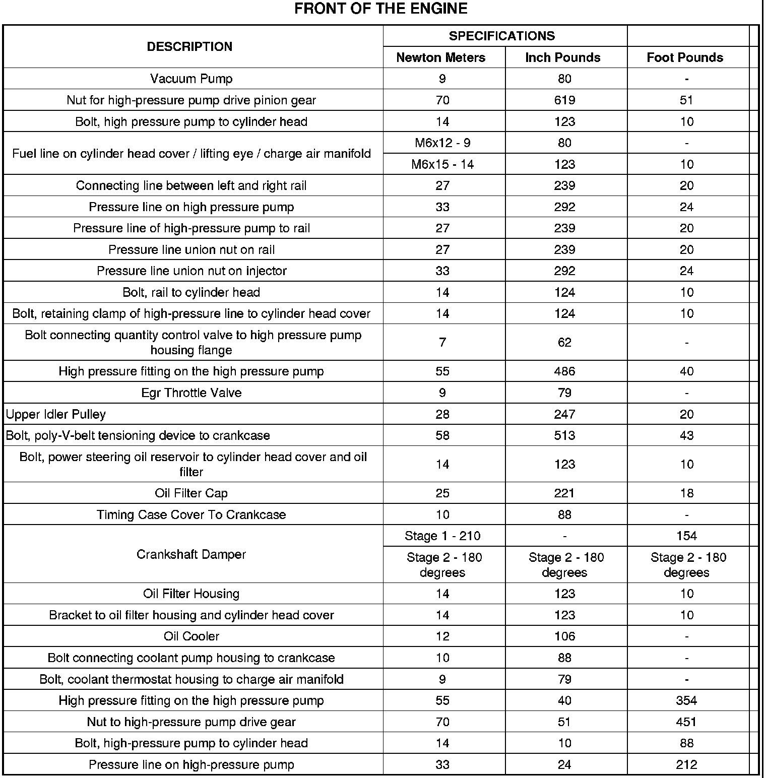

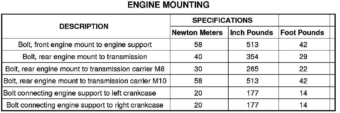
CYLINDER HEAD TORQUE AND SEQUENCE
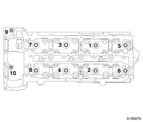
CAUTION: If new cylinder head bolts are used, do not lubricate the new cylinder head bolts. They already are coated with an anti scuff treatment.
Tighten cylinder head bolts following procedure below.
- Tighten M12 cylinder head bolts 1 through 8, in the sequence shown to 60 Nm (44 ft. lbs.).
- Tighten M8 bolts 9 and 10 to 20 Nm ( 177 in. lbs.).
- Tighten M12 cylinder head bolts 1 through 8, in the sequence shown an additional 90 degrees.
- Recheck and tighten M8 bolts 9 and 10 to 20 Nm ( 177 in. lbs.).
- And then again, Tighten M12 cylinder head bolts 1 through 8, in the sequence shown an additional 90 degrees.
CYLINDER HEAD BOLT INSPECTION
1. Measure cylinder head bolts between points shown.
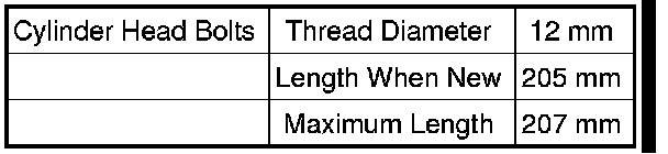

2. If the cylinder head bolt length is greater than the maximum allowable measurement, replace the cylinder head bolts.
INTAKE MANIFOLD TORQUE AND SEQUENCE

CAUTION: The right intake manifold upper thermostat housing bolts should be tightened to 8.4 Nm (74 in. lbs.).
1. Install the intake manifold (4). Tighten bolts to 16 Nm (142 in. lbs.), starting in the middle and tightening in a cross pattern outward until reaching the upper thermostat bolts on the right front manifold.
2. Tighten the upper thermostat bolts on the right cylinder head to 8.4 Nm (74 in.lbs.).
CAMSHAFT RETAINER TORQUE
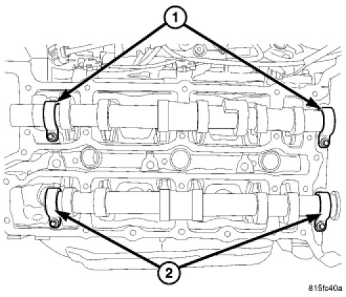
Install the camshaft retainers and tighten each retaining bolt to 9 Nm (80 in. lbs.).
CRANKSHAFT TORQUE AND SEQUENCE

NOTE: Do not reuse the main bearing cap bolts. Always install new bolts.
NOTE: Add a light coating of oil to the crankshaft side of the bearing.
1. Lubricate bolts on the thread and bolt head contact surfaces with engine oil. Install all crankshaft bearing cap bolts finger tight.
2. Stage 1: In the sequence shown in the graphic, tighten the crankshaft bearing cap bolts (1-13) to 35 Nm (26 ft lbs)
3. Stage 2: Turn crankshaft bearing cap bolts an additional 95 degrees.
4. Stage 3: Turn crankshaft bearing cap bolts an additional 95 degrees.
5. Stage 4: In the sequence shown in the graphic, tighten the lateral (side of the block, 1- 8) crankshaft bearing cap bolts to 53 Nm (39 ft lbs).
6. Make sure that the crankshaft turns freely.
CONNECTING ROD TORQUE
HARMONIC BALANCER TORQUE
Tighten the bolt to 304 Nm, plus 90 degrees (224 ft. lbs. plus 90 degrees).
FLEX PLATE TORQUE AND SEQUENCE
Tighten the flex plate fasteners in a cross sequence to 44 Nm (32.5 ft. lbs.).
OIL PUMP TORQUE
Torque fastener to 19 Nm (14 ft. lbs.).
EXHAUST MANIFOLD TORQUE
Torque the nuts to 25 Nm ( 222 in. lbs.)
Factory Service Tools
Use the Manual With the Right Hardware
Pair factory procedures with proven DIY tools so the instructions are easier to execute.
Disclosure: Verified tool recommendations may earn an affiliate commission at no cost to you.
When to See a Mechanic
Stop DIY work and contact a certified mechanic immediately if any of the following apply:
- • You smell fuel, burning insulation, or see smoke.
- • Brakes feel soft, pull hard to one side, or make grinding noises.
- • The engine overheats, stalls repeatedly, or misfires under load.
- • You are missing required tools, torque specs, or safe lifting equipment.
- • You are not confident in the next step or safety outcome.