
Safety Warning
DIY auto repair can cause serious injury, fire, or vehicle damage. These guides are for informational purposes only. Always follow OEM torque specs, wear PPE, and consult a certified mechanic if you are unsure. You are solely responsible for your safety.
2004 Freightliner Sprinter 2500 L5-2.7L DSL TurboFACTORY OEM SERVICE PROCEDURE
System Specifications
Crankshaft
Bolt-Crankshaft Bearing Cap (2 stage, 1 torque, 1 torque angle 55, 90° (40.5, 90°)
Crankshaft center bolt and washer.
Tighten bolt in two stages. M8.8 bolt to 200 Nm (148 ft. lbs.) then 90°, M10.9 bolt to 325 Nm (240 ft. lbs.) then 90°.
CONNECTING ROD SPECIFICATIONS
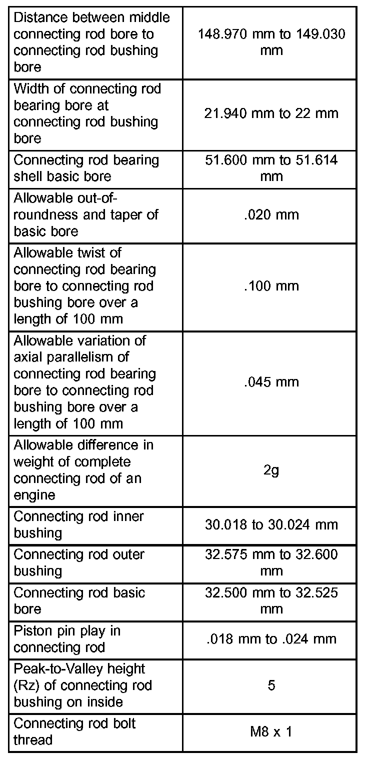
Connecting Rod
Bolt-Connecting Rod Cap to Connecting Rod (3 stage, 1 & 2 torque, 1 torque angle) 5, 25, 90° 44, 221, 90°
Connecting rod bearing cap.
Tighten bolts in 3 stages, 5 Nm (44 inch lbs.), 25 Nm (221 inch lbs.), 90°.
MEASURING CYLINDER BORES

Measure each cylinder at the three measuring points shown (Fig. 30).
Using the three measurement point, measure cylinder in the longitudinal and in the transverse direction (Fig. 30).
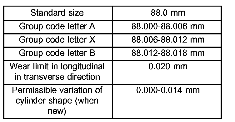
Use the measurement and table below to group cylinder bores:
PISTON RINGS
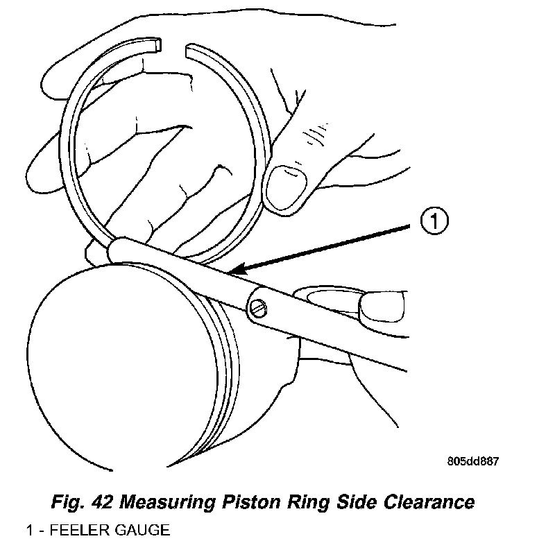
RING SIDE CLEARANCE CHART
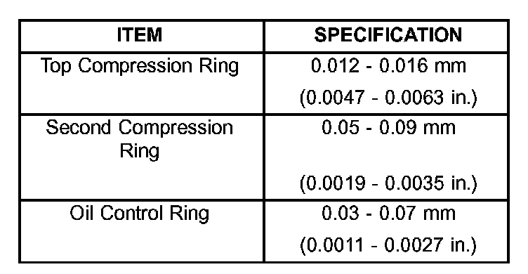
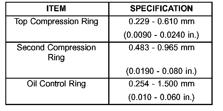
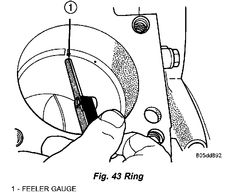
RING GAP MEASUREMENT CHART
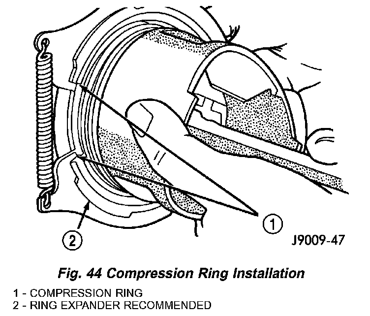
Using a ring expander, install compression rings with manufactures designation pointing toward piston crown (Fig. 44).

Ring Gap Orientation
Bolt-Crankshaft Bearing Cap (2 stage, 1 torque, 1 torque angle 55, 90° (40.5, 90°)
Crankshaft center bolt and washer.
Tighten bolt in two stages. M8.8 bolt to 200 Nm (148 ft. lbs.) then 90°, M10.9 bolt to 325 Nm (240 ft. lbs.) then 90°.
CONNECTING ROD SPECIFICATIONS
Connecting Rod
Bolt-Connecting Rod Cap to Connecting Rod (3 stage, 1 & 2 torque, 1 torque angle) 5, 25, 90° 44, 221, 90°
Connecting rod bearing cap.
Tighten bolts in 3 stages, 5 Nm (44 inch lbs.), 25 Nm (221 inch lbs.), 90°.
MEASURING CYLINDER BORES
Measure each cylinder at the three measuring points shown (Fig. 30).
Using the three measurement point, measure cylinder in the longitudinal and in the transverse direction (Fig. 30).
Use the measurement and table below to group cylinder bores:
PISTON RINGS
RING SIDE CLEARANCE CHART
RING GAP MEASUREMENT CHART
Using a ring expander, install compression rings with manufactures designation pointing toward piston crown (Fig. 44).
Ring Gap Orientation
Factory Service Tools
Use the Manual With the Right Hardware
Pair factory procedures with proven DIY tools so the instructions are easier to execute.
Disclosure: Verified tool recommendations may earn an affiliate commission at no cost to you.
When to See a Mechanic
Stop DIY work and contact a certified mechanic immediately if any of the following apply:
- • You smell fuel, burning insulation, or see smoke.
- • Brakes feel soft, pull hard to one side, or make grinding noises.
- • The engine overheats, stalls repeatedly, or misfires under load.
- • You are missing required tools, torque specs, or safe lifting equipment.
- • You are not confident in the next step or safety outcome.