
Safety Warning
DIY auto repair can cause serious injury, fire, or vehicle damage. These guides are for informational purposes only. Always follow OEM torque specs, wear PPE, and consult a certified mechanic if you are unsure. You are solely responsible for your safety.
2003 Freightliner Sprinter 2500 L5-2.7L DSL TurboFACTORY OEM SERVICE PROCEDURE
Transmission Position Sensor/Switch: Description and Operation
NAG1 TRANSMISSION
TEMPERATURE SENSOR/PARK-NEUTRAL CONTACT
DESCRIPTION
DESCRIPTION - PARK/NEUTRAL CONTACT
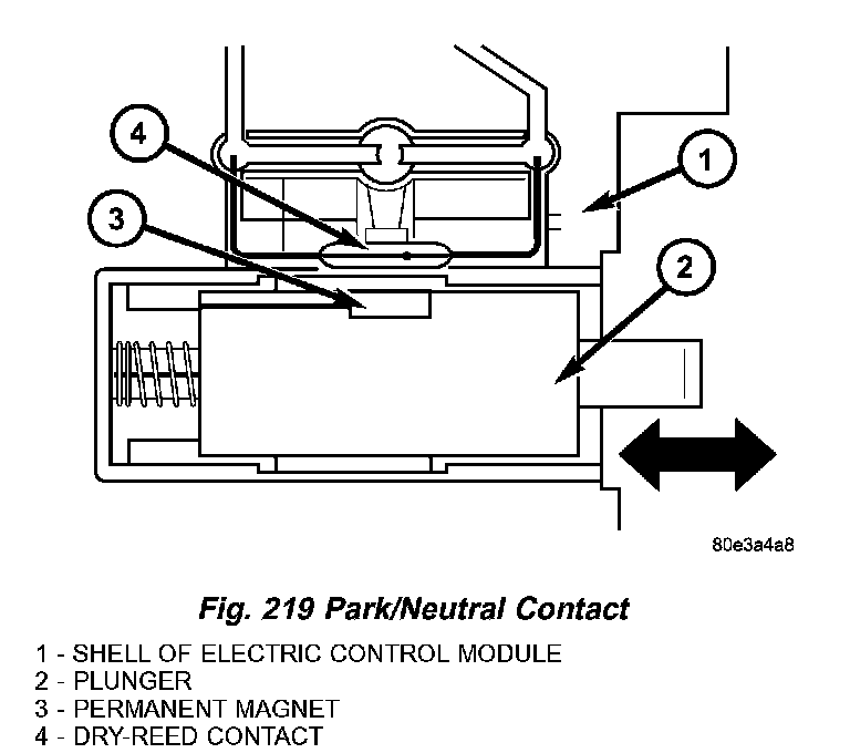
The park/neutral contact (4) (Fig. 219) is located in the shell of the electric control unit and is fixed to the conductor tracks.
Its purpose is to recognize selector valve and selector lever positions "P" and "N". The park/neutral contact consists of:
^ the plunger (2).
^ the permanent magnet (3).
^ the dry-reed contact (4).
DESCRIPTION - TRANSMISSION TEMPERATURE SENSOR
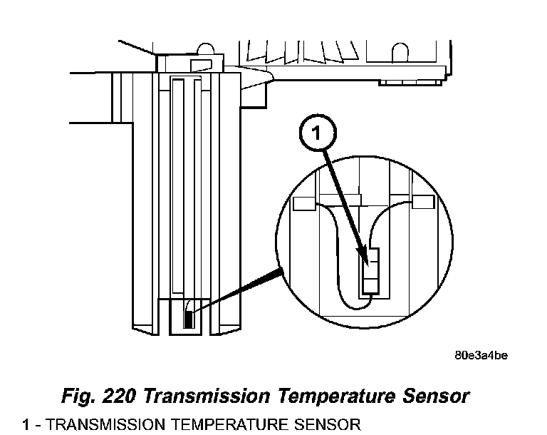
The transmission oil temperature sensor (1) (Fig. 220) is located in the shell of the electric valve control unit and is fixed to the conductor tracks.
Its purpose is to measure the temperature of the transmission oil and pass the temperature to the TCM as an input signal. It is a temperature-dependent resistor (PTC).
OPERATION
OPERATION - PARK/NEUTRAL CONTACT
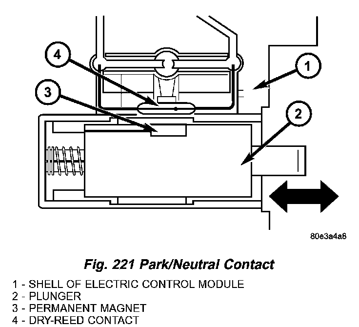
In selector lever positions "P" and "N" the park/ neutral contact (4) (Fig. 221) is actuated by a cam track which is located on the detent plate. The permanent magnet (3) is moved away from the dry-reed contact (4). The dry-reed contact (4) is opened. The TCM receives an electric signal. The circuit to the starter in the selector lever positions "P" and "N" is closed.
OPERATION - TRANSMISSION TEMPERATURE SENSOR
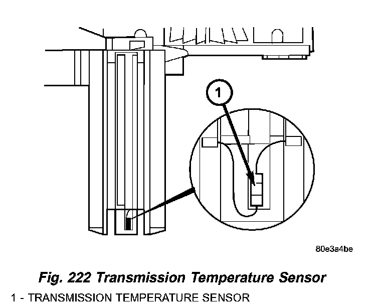
The temperature of the transmission oil has a considerable effect on the shifting time and therefore the shift quality. By measuring the oil temperature, shift operations can be optimized in all temperature ranges. The transmission oil temperature sensor (1) (Fig. 222) is switched in series with the park/neutral contact. The temperature signal is transferred to the TCM only when the dry-reed contact of the park/neutral contact is closed in REVERSE or a forward gear position.
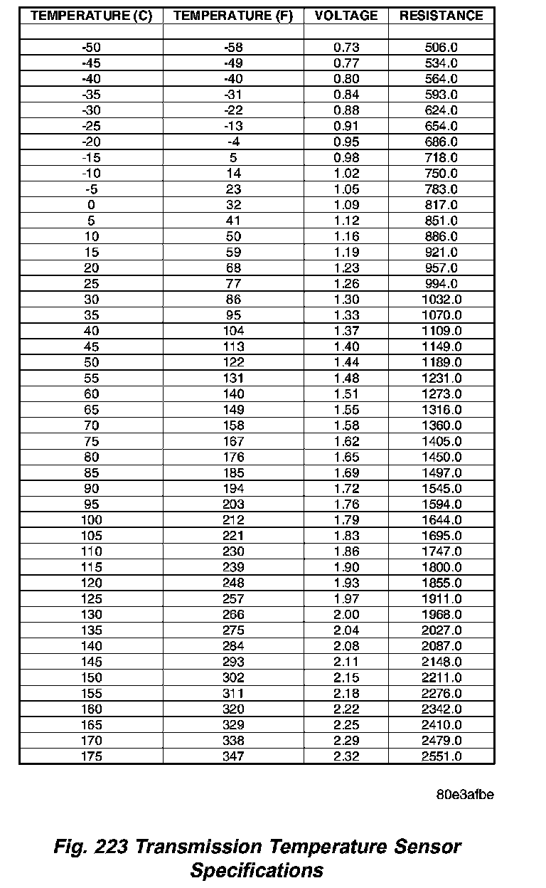
Refer to the Transmission Temperature Sensor Specifications table (Fig. 223) for the relationship between transmission temperature, sensor voltage, and sensor resistance.
TEMPERATURE SENSOR/PARK-NEUTRAL CONTACT
DESCRIPTION
DESCRIPTION - PARK/NEUTRAL CONTACT
The park/neutral contact (4) (Fig. 219) is located in the shell of the electric control unit and is fixed to the conductor tracks.
Its purpose is to recognize selector valve and selector lever positions "P" and "N". The park/neutral contact consists of:
^ the plunger (2).
^ the permanent magnet (3).
^ the dry-reed contact (4).
DESCRIPTION - TRANSMISSION TEMPERATURE SENSOR
The transmission oil temperature sensor (1) (Fig. 220) is located in the shell of the electric valve control unit and is fixed to the conductor tracks.
Its purpose is to measure the temperature of the transmission oil and pass the temperature to the TCM as an input signal. It is a temperature-dependent resistor (PTC).
OPERATION
OPERATION - PARK/NEUTRAL CONTACT
In selector lever positions "P" and "N" the park/ neutral contact (4) (Fig. 221) is actuated by a cam track which is located on the detent plate. The permanent magnet (3) is moved away from the dry-reed contact (4). The dry-reed contact (4) is opened. The TCM receives an electric signal. The circuit to the starter in the selector lever positions "P" and "N" is closed.
OPERATION - TRANSMISSION TEMPERATURE SENSOR
The temperature of the transmission oil has a considerable effect on the shifting time and therefore the shift quality. By measuring the oil temperature, shift operations can be optimized in all temperature ranges. The transmission oil temperature sensor (1) (Fig. 222) is switched in series with the park/neutral contact. The temperature signal is transferred to the TCM only when the dry-reed contact of the park/neutral contact is closed in REVERSE or a forward gear position.
Refer to the Transmission Temperature Sensor Specifications table (Fig. 223) for the relationship between transmission temperature, sensor voltage, and sensor resistance.
Factory Service Tools
Use the Manual With the Right Hardware
Pair factory procedures with proven DIY tools so the instructions are easier to execute.
Disclosure: Verified tool recommendations may earn an affiliate commission at no cost to you.
When to See a Mechanic
Stop DIY work and contact a certified mechanic immediately if any of the following apply:
- • You smell fuel, burning insulation, or see smoke.
- • Brakes feel soft, pull hard to one side, or make grinding noises.
- • The engine overheats, stalls repeatedly, or misfires under load.
- • You are missing required tools, torque specs, or safe lifting equipment.
- • You are not confident in the next step or safety outcome.