
Safety Warning
DIY auto repair can cause serious injury, fire, or vehicle damage. These guides are for informational purposes only. Always follow OEM torque specs, wear PPE, and consult a certified mechanic if you are unsure. You are solely responsible for your safety.
2013 Ford Focus ELE-Electric EngineFACTORY OEM SERVICE PROCEDURE
Front Subframe: Service and Repair
Front Subframe
Removal
NOTICE: Suspension fasteners are critical parts because they affect performance of vital components and systems and their failure may result in major service expense. New parts must be installed with the same part numbers or equivalent part, if replacement is necessary. Do not use a replacement part of lesser quality or substitute design. Torque values must be used as specified during reassembly to make sure of correct retention of these parts.
1. WARNING: Before beginning any service procedure, Failure to follow this instruction may result in serious personal injury.
Refer to: Health and Safety Precautions (100-00 General Information, Description and Operation).
2. NOTICE: Disconnect the battery ground cable anytime the steering gear is being serviced or damage to the steering gear internal power relay may occur resulting in steering gear replacement.
Refer to: Battery Disconnect and Connect (414-01 Battery, Mounting and Cables, General Procedures).
3. Steering wheel in straight ahead position.

4. Refer to: Wheel and Tire (204-04A Wheels and Tires, Removal and Installation).
5. If equipped.

6. On both sides.

7. WARNING: Do not reuse steering column shaft bolts. This may result in fastener failure and steering column shaft detachment or loss of steering control. Failure to follow this instruction may result in serious injury to vehicle occupant(s).
Discard the specified component. Follow local disposal regulations.

8. NOTE:
- The stabilizer bar links are designed with low friction ball joints that have a low breakaway torque.
- Use the hex-holding feature to prevent the ball stud from turning while removing or installing the stabilizer bar link nut.
On both sides. Discard the specified component. Follow local disposal regulations.
Torque: 63 Nm

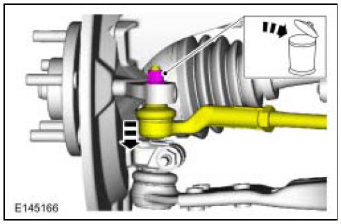
9. NOTICE:
- Do not use a hammer to separate the outer tie-rod end from the wheel knuckle or damage to the wheel knuckle may result.
- Use care when installing the tie rod separator or damage to the outer tie-rod end boot may occur.
On both sides. Discard the specified component. Follow local disposal regulations.
Torque: 48 Nm
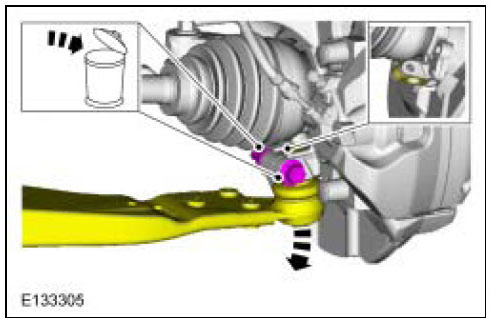
10. NOTICE:
- Do not use a prying device or separator fork between the ball joint and the wheel knuckle. Damage to the ball joint or ball joint seal may result. Only use the pry bar by inserting it into the lower arm body opening.
- Use care when releasing the lower arm and wheel knuckle into the resting position or damage to the ball joint seal may occur.
On both sides. Discard the specified component. Follow local disposal regulations.
11.
12.
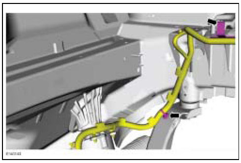
13. General Equipment: Transmission Jack
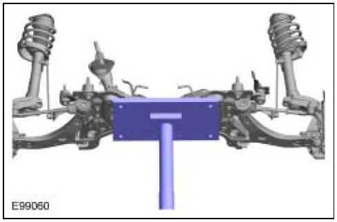
14. Discard the specified component. Follow local disposal regulations.
General Equipment: Transmission Jack
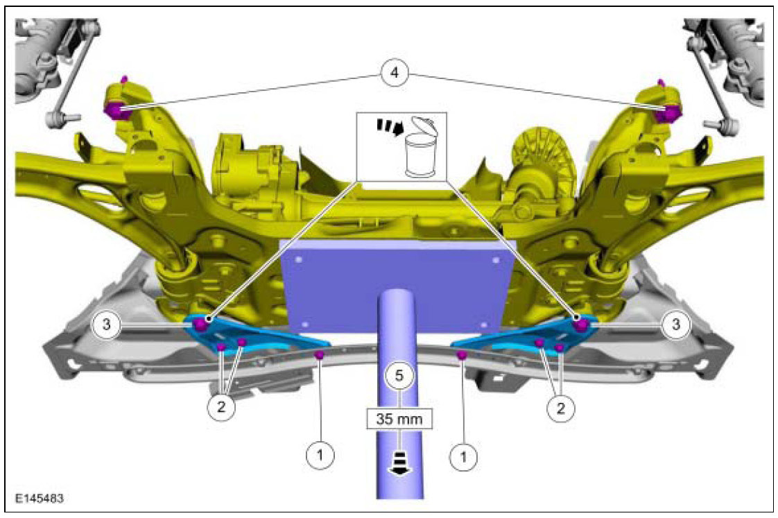
15.

16. General Equipment: Transmission Jack

Installation
1. General Equipment: Transmission Jack

2.

3. Finger tight at this stage.
General Equipment: Transmission Jack

4. NOTE: While tightening the subframe bolts, make sure the front subframe does not move.
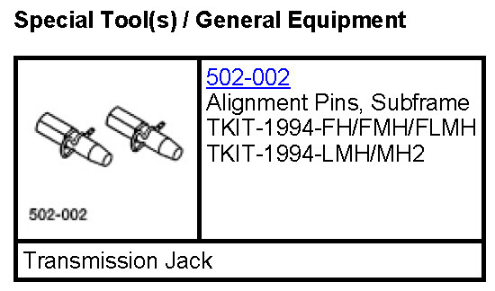
Special Tool(s): 502-002 (Alignment Pins, Subframe)

5. General Equipment: Transmission Jack
Torque:
1. 115 Nm
2. 140 Nm
2. 180°
3. 20 Nm
4. 20 Nm

6.

7. Torque: 86 Nm
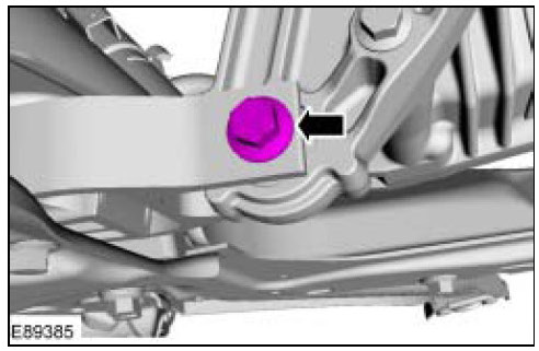
8. On both sides.
Torque: 83 Nm
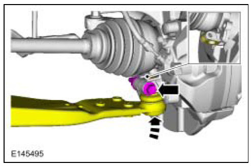
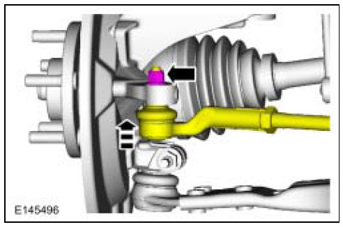
9. On both sides.
Torque: 48 Nm
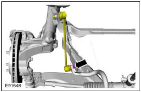
10. NOTE:
- The stabilizer bar links are designed with low friction ball joints that have a low breakaway torque.
- Use the hex-holding feature to prevent the ball stud from turning while removing or installing the stabilizer bar link nut.
On both sides.
Torque: 63 Nm
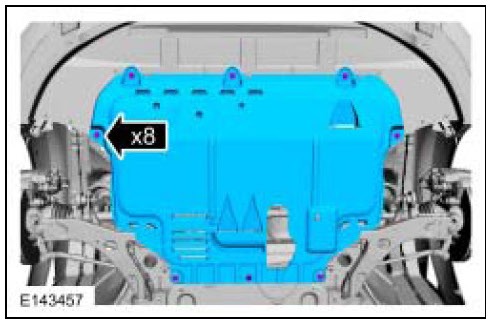
11. Torque: 28 Nm

12. On both sides.
Torque: 25 Nm

13. If equipped.
14. Refer to: Wheel and Tire (204-04A Wheels and Tires, Removal and Installation).
15. Refer to: Battery Disconnect and Connect (414-01 Battery, Mounting and Cables, General Procedures).
16. Refer to: Front Toe Adjustment (204-00 Suspension System - General Information, General Procedures).
Factory Service Tools
Use the Manual With the Right Hardware
Pair factory procedures with proven DIY tools so the instructions are easier to execute.
Disclosure: Verified tool recommendations may earn an affiliate commission at no cost to you.
When to See a Mechanic
Stop DIY work and contact a certified mechanic immediately if any of the following apply:
- • You smell fuel, burning insulation, or see smoke.
- • Brakes feel soft, pull hard to one side, or make grinding noises.
- • The engine overheats, stalls repeatedly, or misfires under load.
- • You are missing required tools, torque specs, or safe lifting equipment.
- • You are not confident in the next step or safety outcome.
Rather have a pro handle this?
A certified mobile mechanic comes to your home or office. They bring the tools, you stay comfortable. No tow truck, no waiting room, no surprises.
Comes to youSame-day available12-month warranty
Get a Free QuoteNo obligation. See pricing before you book.