
Safety Warning
DIY auto repair can cause serious injury, fire, or vehicle damage. These guides are for informational purposes only. Always follow OEM torque specs, wear PPE, and consult a certified mechanic if you are unsure. You are solely responsible for your safety.
2013 Ford Edge FWD L4-2.0L TurboFACTORY OEM SERVICE PROCEDURE
Front Subframe: Service and Repair
Subframe - Front, 2.0L GTDI
General Equipment
Powertrain Lift
Steering Wheel Holder

Removal
NOTICE:
- Suspension and subframe fasteners are critical parts specially designed for the purpose. Replacement fasteners must be identical to the original equipment and torqued as specified. Poor quality or improperly tightened fasteners may fail in service, resulting in vehicle damage and major repair expense.
- When repairing the power steering system, care should be taken to prevent the entry of foreign material or failure of the power steering components may result.
NOTE: Removal steps in this procedure may contain installation details.
1. NOTICE: Do not allow the steering column to rotate while the steering column shaft is disconnected, or damage to the clockspring may occur. If there is evidence that the steering column has rotated, the clockspring must be removed and recentered.
Steering wheel in straight ahead position.
General Equipment: Steering Wheel Holder.

2. Remove the wheel and tire.
3.
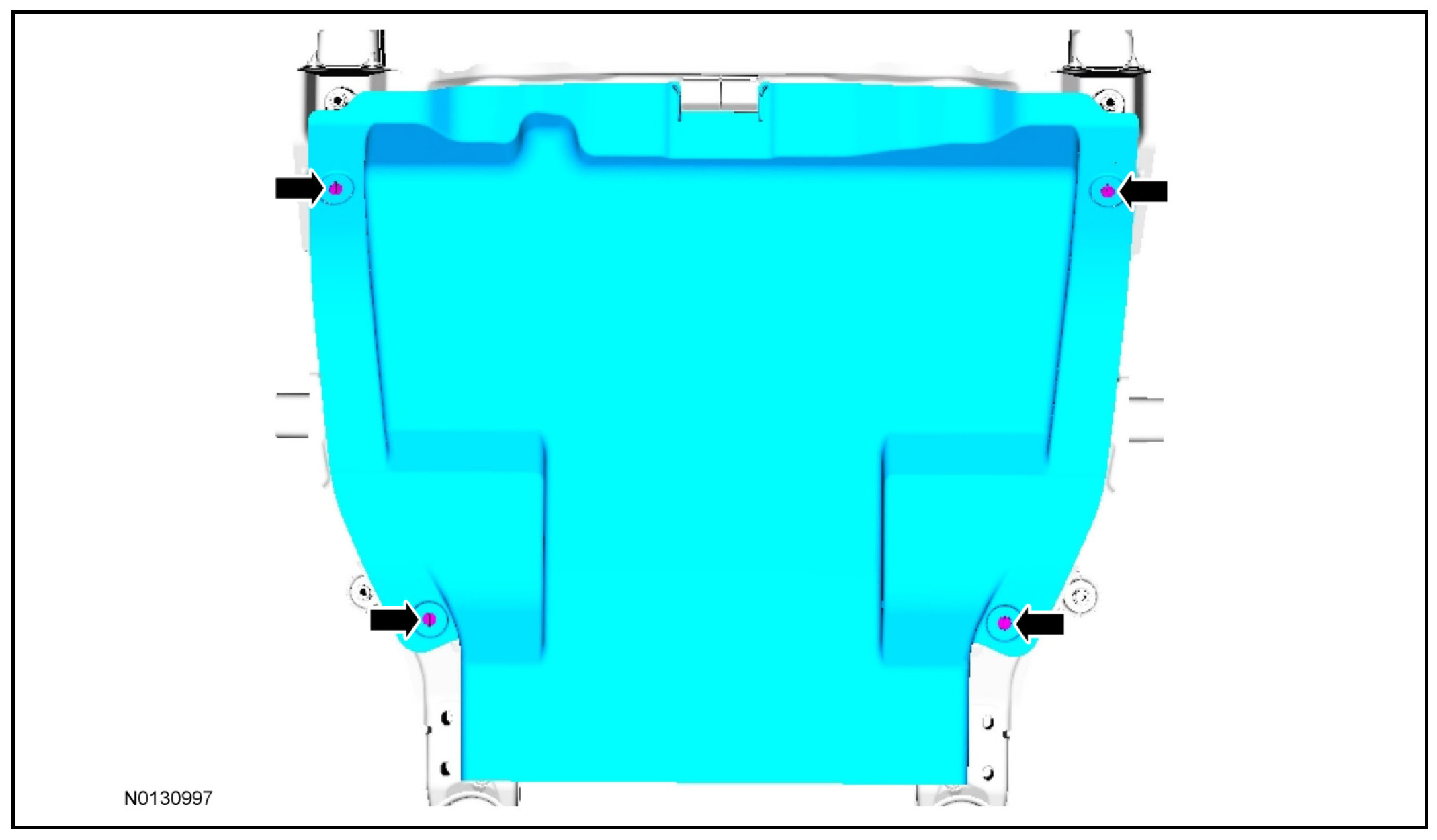
4. WARNING: Do not reuse steering column shaft bolts. This may result in fastener failure and steering column shaft detachment or loss of steering control. Failure to follow this instruction may result in serious injury to vehicle occupant(s).
Discard the specified component. Follow local disposal regulations.
- To install, tighten the new bolt to 25 Nm (18 lb-ft).

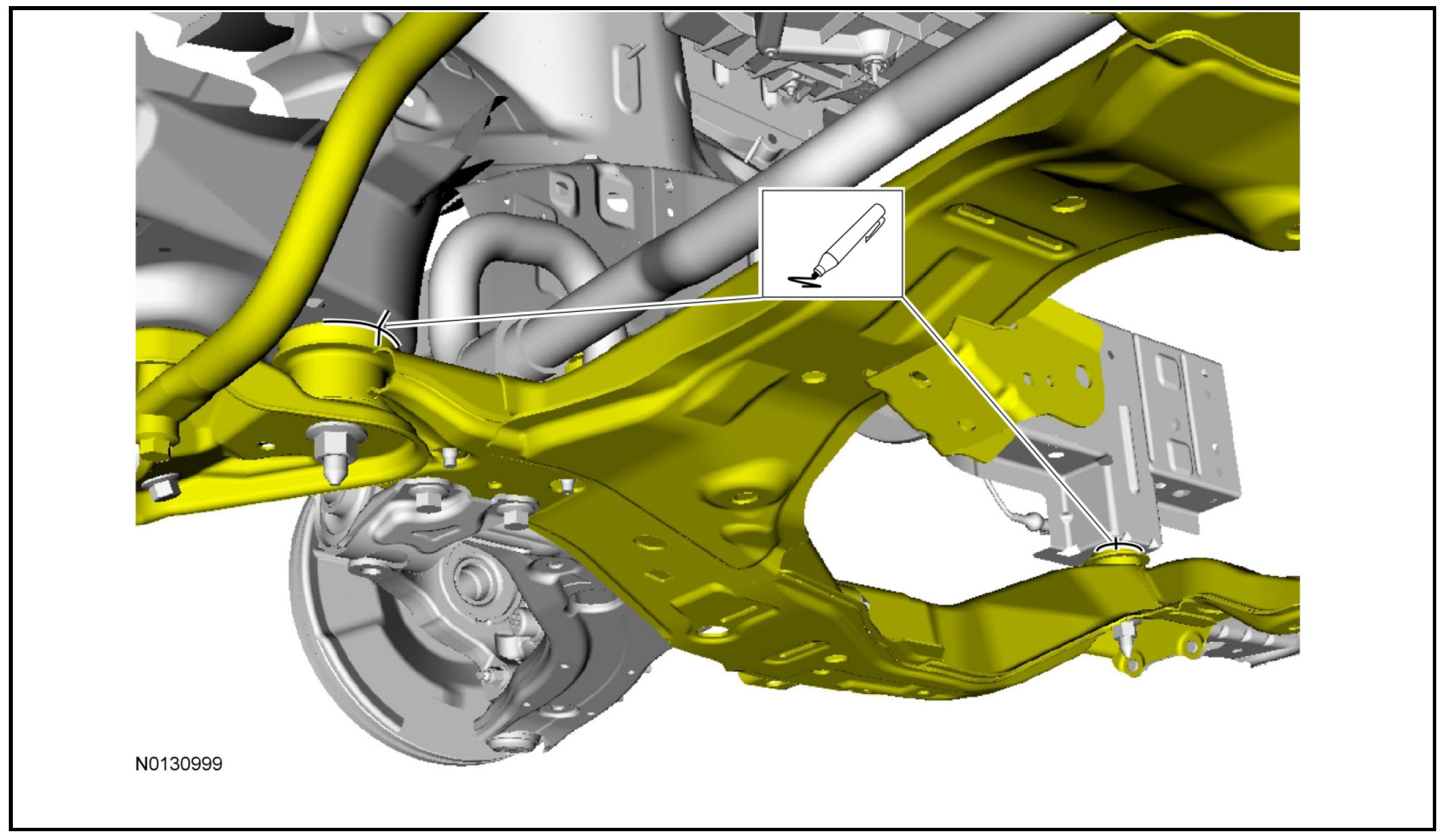
5. On both sides. Marker.
6.
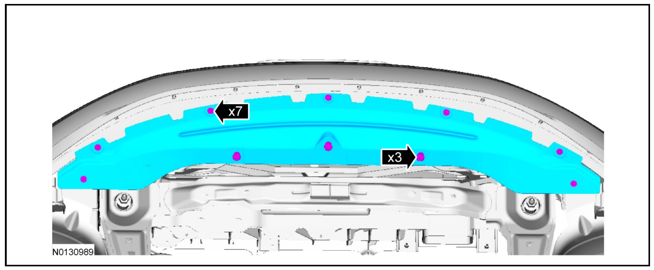
7.

8.

9.
- To install, tighten to 9 Nm (80 lb-in).

10. On both sides.
- To install, tighten to 9 Nm (80 lb-in).

11. Discard the specified component. Follow local disposal regulations.
- To install, tighten the new bolt to 26 Nm (19 lb-ft).

12. On both sides. Discard the specified component. Follow local disposal regulations.
- To install, tighten the new nuts to 48 Nm (35 lb-ft).

13. On both sides.
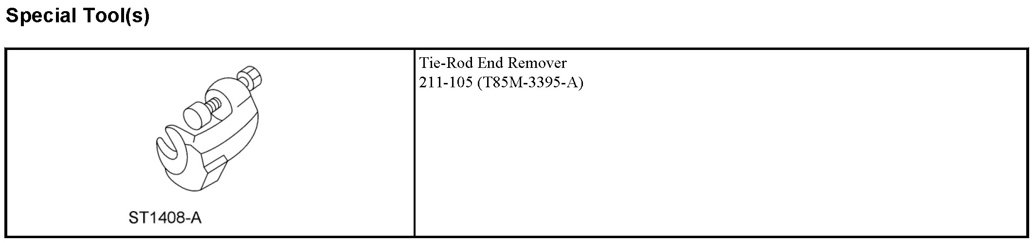
Special Tool(s): Tie Rod End Remover 211-105 (T85M-3395-A).

14. On both sides. Discard the specified component. Follow local disposal regulations.
- To install, tighten the new nuts and bolts to 55 Nm (41 lb-ft).

15. Wire brush. Apply the substance from the specified tube.
Material: Threadlock and Sealer TA-25.
- To install, tighten to 115 Nm (85 lb-in).

16. General Equipment: Powertrain Lift.

17. On both sides. Discard the specified component. Follow local disposal regulations.
- To install, tighten the new bolts to 90 Nm (66 lb-ft).

18. Discard the specified component. Follow local disposal regulations.
- To install, review the unique instructions and illustration in the installation procedure.

19. Discard the specified component. Follow local disposal regulations.
- To install, tighten the new nuts to 133 Nm (98 lb-ft).

20. On both sides. Discard the specified component. Follow local disposal regulations.
- To install, tighten the new nuts to 133 Nm (98 lb-ft).

21. General Equipment: Powertrain Lift.
- To install, align the subframe to the marks on the uni-body.

Installation
1. To install, reverse the removal procedure.
2. Loosely install all fasteners before tightening.
1. Tighten the new nuts to 133 Nm (98 lb-ft).
2. Tighten the new bolts to 90 Nm (66 lb-ft).

3. Fill the power steering system.
Factory Service Tools
Use the Manual With the Right Hardware
Pair factory procedures with proven DIY tools so the instructions are easier to execute.
Disclosure: Verified tool recommendations may earn an affiliate commission at no cost to you.
When to See a Mechanic
Stop DIY work and contact a certified mechanic immediately if any of the following apply:
- • You smell fuel, burning insulation, or see smoke.
- • Brakes feel soft, pull hard to one side, or make grinding noises.
- • The engine overheats, stalls repeatedly, or misfires under load.
- • You are missing required tools, torque specs, or safe lifting equipment.
- • You are not confident in the next step or safety outcome.