
Safety Warning
DIY auto repair can cause serious injury, fire, or vehicle damage. These guides are for informational purposes only. Always follow OEM torque specs, wear PPE, and consult a certified mechanic if you are unsure. You are solely responsible for your safety.
2012 Ford Taurus FWD V6-3.5LFACTORY OEM SERVICE PROCEDURE
Pinpoint Test S: The Side Obstacle Detection Control Module - Right (SOD-R) Does Not Respond To The Scan Tool
Communications Network
Pinpoint Test S: The Side Obstacle Detection Control Module - Right (SOD-R) Does Not Respond To The Scan Tool
Refer to Wiring Diagram Set 14, Module Communications Network for schematic and connector information. Diagrams By Number
Refer to Wiring Diagram Set 136, Vehicle Emergency Messaging System for schematic and connector information. Diagrams By Number
Normal Operation
The Side Obstacle Detection Control Module - Right (SOD-R) communicates with the scan tool through the Medium Speed Controller Area Network (MS-CAN).
This pinpoint test is intended to diagnose the following:
- Fuse
- Wiring, terminals or connectors
- SOD-R (Side Obstacle Detection Control Module - Right)
PINPOINT TEST S : THE SOD-R (Side Obstacle Detection Control Module - Right) DOES NOT RESPOND TO THE SCAN TOOL
NOTICE: Use the correct probe adapter(s) when making measurements. Failure to use the correct probe adapter(s) may damage the connector.
NOTE: Failure to disconnect the battery when instructed will result in false resistance readings.
S1 CHECK THE SOD-R (Side Obstacle Detection Control Module - Right) VOLTAGE SUPPLY CIRCUIT FOR AN OPEN
- Ignition OFF.
- Disconnect: SOD-R (Side Obstacle Detection Control Module - Right) C4370.
- Ignition ON.
- Measure the voltage between the SOD-R (Side Obstacle Detection Control Module - Right) C4370-2, circuit CBP35 (YE/GY), harness side and ground.
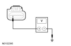
Is the voltage greater than 10 volts?
Yes
GO to S2.
No
VERIFY the Smart Junction Box (SJB) fuse 35 (10A) is OK. If OK, REPAIR the circuit in question. If not OK, Refer to the Wiring Diagrams to identify the possible causes of the circuit short. CLEAR the DTCs. REPEAT the network test with the scan tool. Diagrams By Number
S2 CHECK THE SOD-R (Side Obstacle Detection Control Module - Right) GROUND CIRCUIT FOR AN OPEN
- Ignition OFF.
- Disconnect: Negative Battery Cable.
- Measure the resistance between the SOD-R (Side Obstacle Detection Control Module - Right) C4370-5, circuit GD148 (BK/YE), harness side and ground.
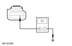
Is the resistance less than 5 ohms?
Yes
GO to S3.
No
REPAIR the circuit. CONNECT the negative battery cable. CLEAR the DTCs. REPEAT the network test with the scan tool.
S3 CHECK THE MS-CAN (Medium Speed Controller Area Network) CIRCUITS BETWEEN THE SOD-R (Side Obstacle Detection Control Module - Right) AND THE DLC (Data Link Connector) FOR AN OPEN
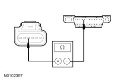
- Measure the resistance between the SOD-R (Side Obstacle Detection Control Module - Right) C4370-3, circuit VDB06 (GY/OG), harness side and the Data Link Connector (DLC) C251-3, circuit VDB06 (GY/OG), harness side.
- Measure the resistance between the SOD-R (Side Obstacle Detection Control Module - Right) C4370-4, circuit VDB07 (VT/OG), harness side and the DLC (Data Link Connector) C251-11, circuit VDB07 (VT/OG), harness side.
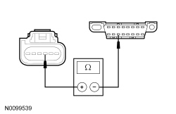
Are the resistances less than 5 ohms?
Yes
CONNECT the negative battery cable. GO to S4.
No
REPAIR the circuit in question. CONNECT the negative battery cable. CLEAR the DTCs. REPEAT the network test with the scan tool.
S4 CHECK FOR CORRECT SOD-R (Side Obstacle Detection Control Module - Right) OPERATION
- Disconnect the SOD-R (Side Obstacle Detection Control Module - Right) connector.
- Check for:
- corrosion
- damaged pins
- pushed-out pins
- Connect the SOD-R (Side Obstacle Detection Control Module - Right) connector and make sure it seats correctly.
- Operate the system and verify the concern is still present.
Is the concern still present?
Yes
INSTALL a new SOD-R (Side Obstacle Detection Control Module - Right). CLEAR the DTCs. REPEAT the network test with the scan tool.
No
The system is operating correctly at this time. The concern may have been caused by a loose or corroded connector.
Factory Service Tools
Use the Manual With the Right Hardware
Pair factory procedures with proven DIY tools so the instructions are easier to execute.
Disclosure: Verified tool recommendations may earn an affiliate commission at no cost to you.
When to See a Mechanic
Stop DIY work and contact a certified mechanic immediately if any of the following apply:
- • You smell fuel, burning insulation, or see smoke.
- • Brakes feel soft, pull hard to one side, or make grinding noises.
- • The engine overheats, stalls repeatedly, or misfires under load.
- • You are missing required tools, torque specs, or safe lifting equipment.
- • You are not confident in the next step or safety outcome.