
Safety Warning
DIY auto repair can cause serious injury, fire, or vehicle damage. These guides are for informational purposes only. Always follow OEM torque specs, wear PPE, and consult a certified mechanic if you are unsure. You are solely responsible for your safety.
2012 Ford Mustang V6-3.7LFACTORY OEM SERVICE PROCEDURE
Fuel Level Sender
Fuel Level Sender
3.7L and 5.0L (4V) vehicles

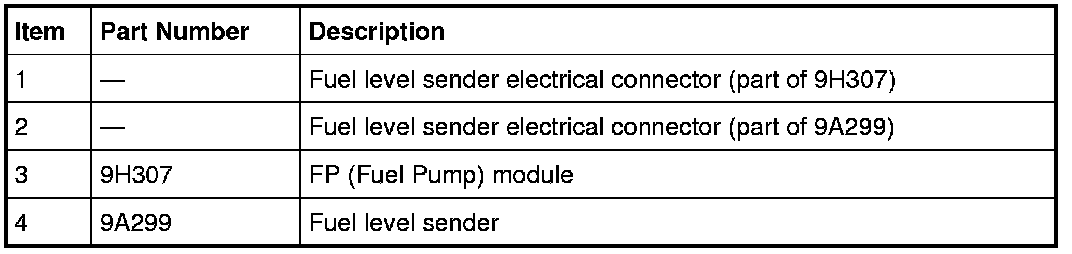
5.4L (4V) vehicles
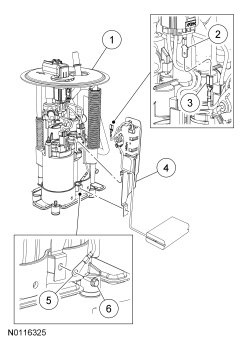
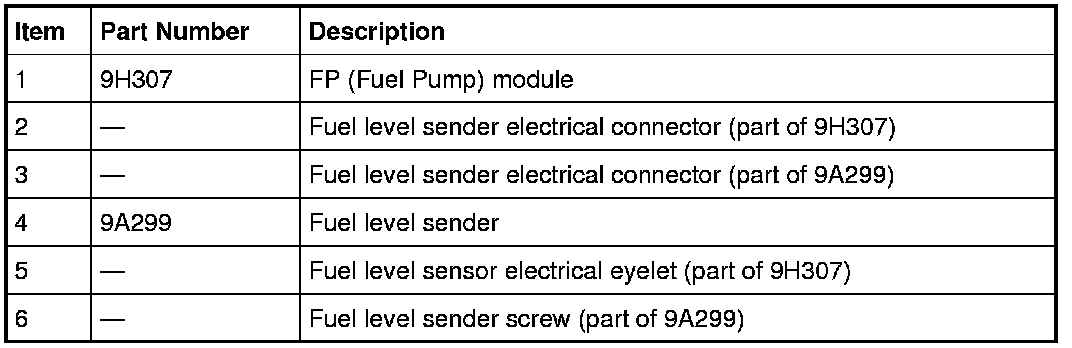
Removal
WARNING: Do not smoke, carry lighted tobacco or have an open flame of any type when working on or near any fuel-related component. Highly flammable mixtures are always present and may be ignited. Failure to follow these instructions may result in serious personal injury.
WARNING: Do not carry personal electronic devices such as cell phones, pagers or audio equipment of any type when working on or near any fuel-related component. Highly flammable mixtures are always present and may be ignited. Failure to follow these instructions may result in serious personal injury.
WARNING: When handling fuel, always observe fuel handling precautions and be prepared in the event of fuel spillage. Spilled fuel may be ignited by hot vehicle components or other ignition sources. Failure to follow these instructions may result in serious personal injury.
WARNING: Always disconnect the battery ground cable at the battery when working on an evaporative emission (EVAP) system or fuel-related component. Highly flammable mixtures are always present and may be ignited. Failure to follow these instructions may result in serious personal injury.
All vehicles
1. Remove the FP (Fuel Pump) module. For additional information, refer to Fuel Pump Module Service and Repair.
3.7L and 5.0L (4V) vehicles
2. Disconnect the fuel level sender electrical connector.
- Note the fuel level sender wire routing and retention clip locations for installation.
3. Remove the wires from the retention clip.
4. Depress the lock tab and remove the fuel level sender from the FP (Fuel Pump) module.
5.4L (4V) vehicles
5. Remove the heat shrink tube covering the fuel level sender wire electrical connector.
- Note the fuel level sender wire routing for installation.
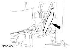
6. Disconnect the fuel level sender wire electrical connector.
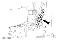
7. Remove the screw, the fuel level sender ground wire and lift up on the fuel level sender to remove it from the FP (Fuel Pump) module.
- Note the fuel level sender wire routing for installation.
Installation
5.4L (4V) vehicles
1. Install the fuel level sender, fuel level sender ground wire and tighten the screw.
2. Slide the heat shrink tube onto the wire harness and connect the fuel level sender wire electrical connector.
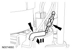
3. WARNING: Do not use an open flame to shrink the heat shrink tube. Use a heat gun only. Fuel residue may be ignited if an open flame is used. Failure to follow this instruction may result in serious personal injury.
Using a heat gun, shrink the heat shrink tube.
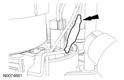
3.7L and 5.0L (4V) vehicles
4. Install the fuel level sender onto the FP (Fuel Pump) module.
5. Position the wires into the retention clip.
6. Connect the fuel level sender electrical connector.
All vehicles
7. Install the FP (Fuel Pump) module. For additional information, refer to Fuel Pump Module Service and Repair.
Factory Service Tools
Use the Manual With the Right Hardware
Pair factory procedures with proven DIY tools so the instructions are easier to execute.
Disclosure: Verified tool recommendations may earn an affiliate commission at no cost to you.
When to See a Mechanic
Stop DIY work and contact a certified mechanic immediately if any of the following apply:
- • You smell fuel, burning insulation, or see smoke.
- • Brakes feel soft, pull hard to one side, or make grinding noises.
- • The engine overheats, stalls repeatedly, or misfires under load.
- • You are missing required tools, torque specs, or safe lifting equipment.
- • You are not confident in the next step or safety outcome.