
Safety Warning
DIY auto repair can cause serious injury, fire, or vehicle damage. These guides are for informational purposes only. Always follow OEM torque specs, wear PPE, and consult a certified mechanic if you are unsure. You are solely responsible for your safety.
2012 Ford Fiesta L4-1.6LFACTORY OEM SERVICE PROCEDURE
Axle Shaft Assembly
Halfshaft - Exploded View

Wheel End Components
NOTICE: Suspension fasteners are critical parts because they affect performance of vital components and systems and their failure may result in major service expense. New parts must be installed with the same part numbers or equivalent part, if replacement is necessary. Do not use a replacement part of lesser quality or substitute design. Torque values must be used as specified during reassembly to make sure correct retention of these parts.
NOTICE: Do not tighten the wheel hub nut with the vehicle on the ground. Tighten the nut to specification before the vehicle is lowered onto the wheels. Wheel bearing damage will occur if the wheel bearing is loaded with the weight of the vehicle applied.
NOTICE: Install and tighten the new wheel hub nut to specification in a continuous rotation. Always install a new wheel hub nut after loosening or when not tightened to specification in a continuous rotation or damage to the components may occur.
NOTE: Apply the brake to keep the halfshaft from rotating while tightening the wheel hub nut.
NOTE: LH shown, RH similar.
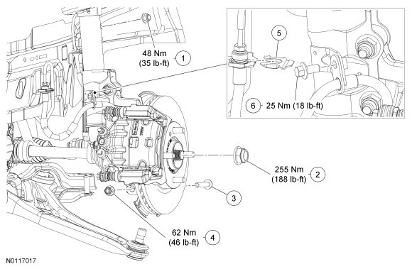
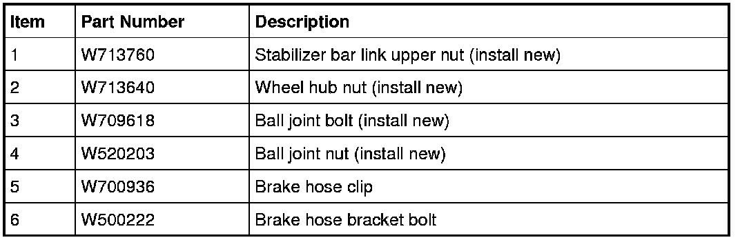
Halfshafts
NOTICE: Install the bearing retainer strap (item 4) on the bracket studs before the shield (item 3) and tighten the nuts evenly in stages (alternating from top to bottom) or incorrect bearing clampload may occur causing component damage.
NOTICE: The inner joint must not be bent more than 18 degrees. The outer joint must not be bent more than 45 degrees. Damage to the halfshaft will occur.
NOTICE: Install a new halfshaft seal any time the halfshaft is removed from the transmission/transaxle or a leak may occur.
NOTE: Install the RH halfshaft shield so the clip is seated in the notch on the support bracket.
NOTE: For halfshaft CV boot service, refer to Halfshaft - RH Halfshaft - RH or Halfshaft - LH EG Halfshaft - LH.
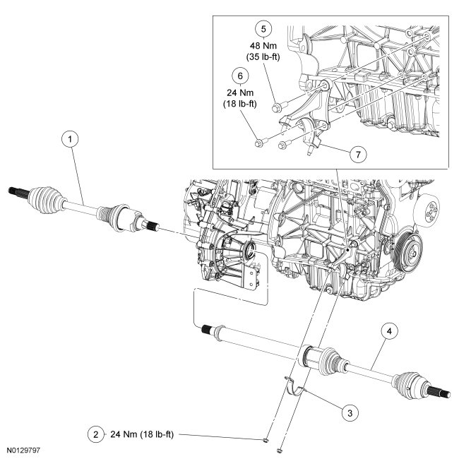
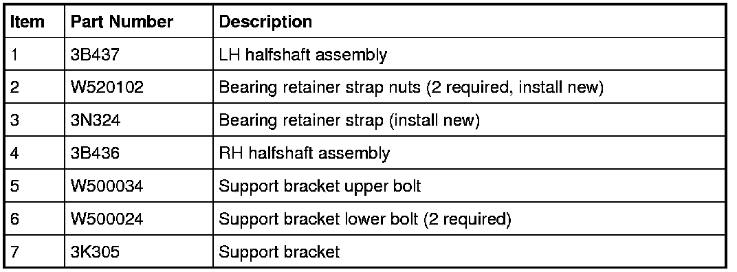
Removal and Installation
1. Refer to the procedures and/or exploded views for any Warnings, Notices, Notes, Materials, Specifications and Special Tools. Items in the exploded views may not be listed in order of removal.
2. With the vehicle in NEUTRAL, position it on a hoist.
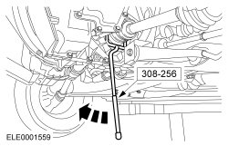
3. Vehicles equipped with a manual transmission, use special tool 308-256 to detach the LH halfshaft.
Factory Service Tools
Use the Manual With the Right Hardware
Pair factory procedures with proven DIY tools so the instructions are easier to execute.
Disclosure: Verified tool recommendations may earn an affiliate commission at no cost to you.
When to See a Mechanic
Stop DIY work and contact a certified mechanic immediately if any of the following apply:
- • You smell fuel, burning insulation, or see smoke.
- • Brakes feel soft, pull hard to one side, or make grinding noises.
- • The engine overheats, stalls repeatedly, or misfires under load.
- • You are missing required tools, torque specs, or safe lifting equipment.
- • You are not confident in the next step or safety outcome.