
Safety Warning
DIY auto repair can cause serious injury, fire, or vehicle damage. These guides are for informational purposes only. Always follow OEM torque specs, wear PPE, and consult a certified mechanic if you are unsure. You are solely responsible for your safety.
2012 Ford F 150 2WD V6-3.7LFACTORY OEM SERVICE PROCEDURE
Engine Control Module: Service and Repair
Powertrain Control Module (PCM)
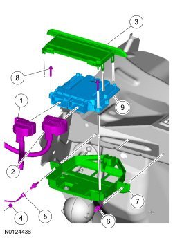
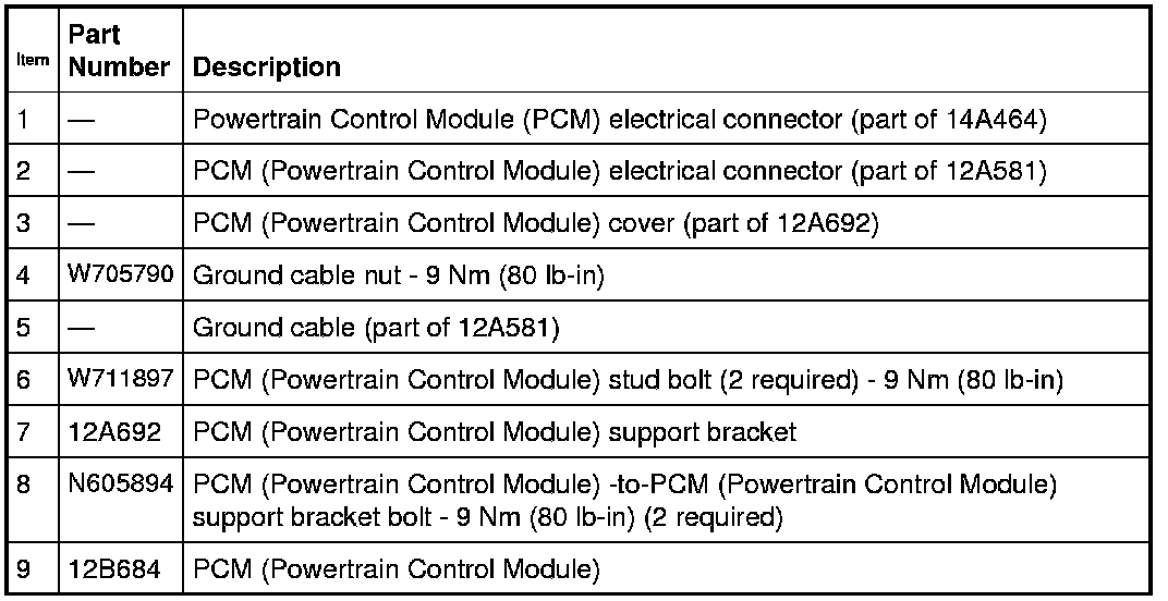
3.5L Gasoline Turbocharged Direct Injection (GTDI) Powertrain Control Module (PCM)
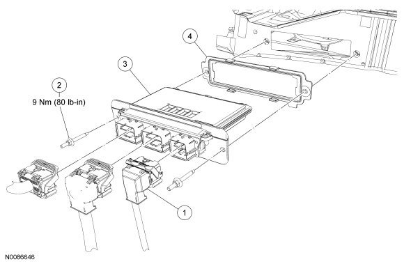
3.7L, 5.0L (4V) and 6.2L (2V) Powertrain Control Module (PCM)

Removal
All engines
1. Retrieve the module configuration. Carry out the module configuration retrieval steps of the Programmable Module Installation (PMI) procedure. For additional information, refer to Information Bus.
Vehicles equipped with a 3.5L Gasoline Turbocharged Direct Injection (GTDI) engine
2. Disconnect the 2 Powertrain Control Module (PCM) electrical connectors.
3. Disengage and remove the PCM (Powertrain Control Module) cover.
4. Remove the 2 PCM (Powertrain Control Module) -to-PCM (Powertrain Control Module) support bracket bolts and the PCM (Powertrain Control Module).
5. If the PCM support bracket is damaged, remove the nut and position the ground cable aside and remove the 2 PCM (Powertrain Control Module) stud bolts and slide the PCM (Powertrain Control Module) support bracket out of the bulkhead.
Vehicles equipped with a 3.7L, 5.0L (4V) or 6.2L (2V) engine
6. Disconnect the Powertrain Control Module (PCM) electrical connectors.
7. Remove the stud bolts, the PCM (Powertrain Control Module) and the gasket.
Installation
Vehicles equipped with a 3.7L, 5.0L (4V) or 6.2L (2V) engine
1. Install the gasket, the PCM (Powertrain Control Module) and the 2 stud bolts.
- Tighten to 9 Nm (80 lb-in).
2. Connect the PCM (Powertrain Control Module) electrical connectors.
Vehicles equipped with a 3.5L Gasoline Turbocharged Direct Injection (GTDI) engine
3. If the PCM (Powertrain Control Module) support bracket was removed, position the support bracket assembly into the bulkhead and install the 2 stud bolts.
- Tighten to 9 Nm (80 lb-in).
4. If the PCM (Powertrain Control Module) support bracket was removed, position the ground cable and install the nut.
- Tighten to 9 Nm (80 lb-in).
5. Position the PCM (Powertrain Control Module) onto the support bracket and install the 2 bolts.
- Tighten to 9 Nm (80 lb-in).
6. Install the PCM (Powertrain Control Module) cover.
7. Connect the 2 PCM (Powertrain Control Module) electrical connectors.
All engines
8. Carry out the transmission solenoid body strategy identification. For additional Information, refer to Automatic Transmission/Transaxle &/or Transmission Control Systems. Solenoid Body Strategy
9. NOTE: If the Programmable Module Installation (PMI) procedure was not successful in downloading the data from the vehicles original PCM, then the oil life data of the vehicle is lost. If this occurs, and the oil life cannot be determined through service history or customer interview, it is recommended the vehicle engine oil and filter be changed and the oil change minder reset.
Restore the module configuration. Carry out the module configuration restore steps of the Programmable Module Installation (PMI) procedure. For additional information, refer to Information Bus.
10. Perform the Passive Anti-Theft System (PATS) Parameter Reset procedure. For additional information, refer to Antitheft and Alarm Systems.
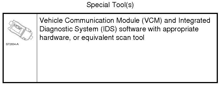
11. Using the scan tool, perform the Misfire Monitor Neutral Profile Correction procedure, following the on-screen instructions.
Factory Service Tools
Use the Manual With the Right Hardware
Pair factory procedures with proven DIY tools so the instructions are easier to execute.
Disclosure: Verified tool recommendations may earn an affiliate commission at no cost to you.
When to See a Mechanic
Stop DIY work and contact a certified mechanic immediately if any of the following apply:
- • You smell fuel, burning insulation, or see smoke.
- • Brakes feel soft, pull hard to one side, or make grinding noises.
- • The engine overheats, stalls repeatedly, or misfires under load.
- • You are missing required tools, torque specs, or safe lifting equipment.
- • You are not confident in the next step or safety outcome.