
Safety Warning
DIY auto repair can cause serious injury, fire, or vehicle damage. These guides are for informational purposes only. Always follow OEM torque specs, wear PPE, and consult a certified mechanic if you are unsure. You are solely responsible for your safety.
2012 Ford F 150 2WD V6-3.7LFACTORY OEM SERVICE PROCEDURE
Computers and Control Systems
Engine Control Components - Exploded View, 3.7L
Camshaft Position (CMP) Sensor
NOTE: It is necessary to remove the upper intake manifold to access the RH exhaust or intake Camshaft Position (CMP) sensor. For additional information, refer to Engine.
NOTE: LH shown, RH similar.
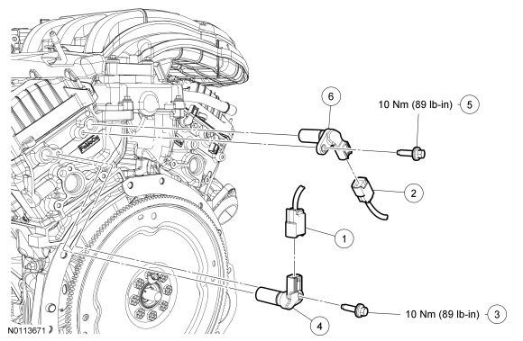
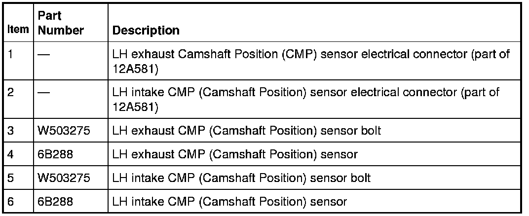
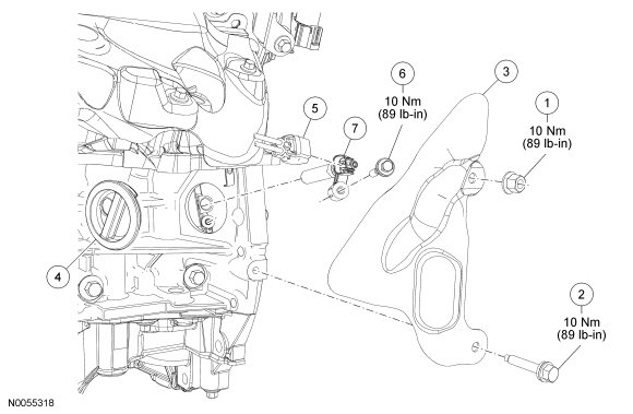
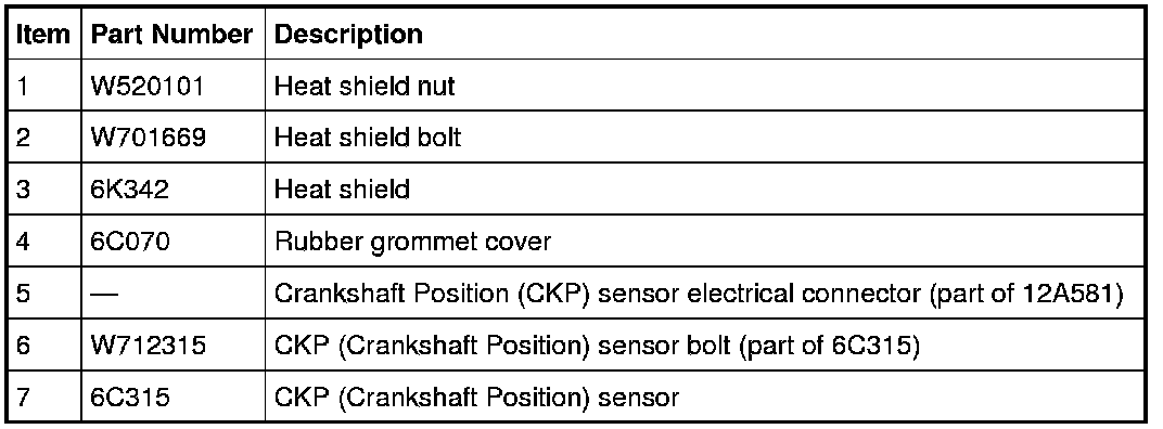
Crankshaft Position (CKP) Sensor
NOTE: After installing the Crankshaft Position (CKP) sensor, use the scan tool to perform the Misfire Monitor Neutral Profile Correction procedure, following the on-screen instructions.
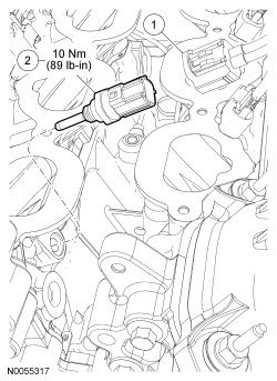
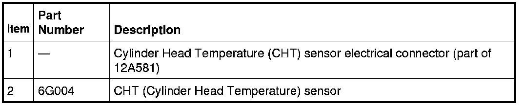
Cylinder Head Temperature (CHT) Sensor
NOTE: It is necessary to remove the lower intake manifold to access the Cylinder Head Temperature (CHT) sensor. For additional information, refer to Engine.
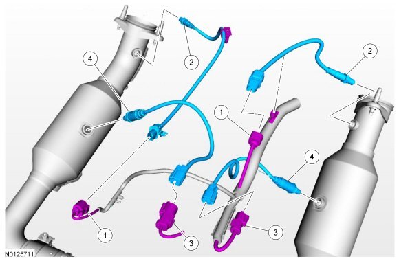
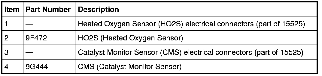
Heated Oxygen Sensor (HO2S) and Catalyst Monitor Sensor (CMS)
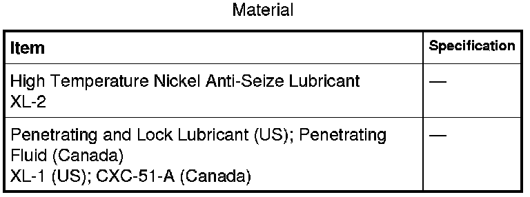
NOTE: If necessary, lubricate the Heated Oxygen Sensor (HO2S) and/or Catalyst Monitor Sensor (CMS) with penetrating and lock lubricant to assist in removal.
NOTE: Apply anti-seize to the threads of the HO2S (Heated Oxygen Sensor) and/or CMS (Catalyst Monitor Sensor) prior to installing.
NOTE: The correct torque wrench setting must be calculated when using the Exhaust Gas Oxygen Sensor Socket to install the HO2S (Heated Oxygen Sensor) and/or CMS (Catalyst Monitor Sensor).
Knock Sensor (KS)
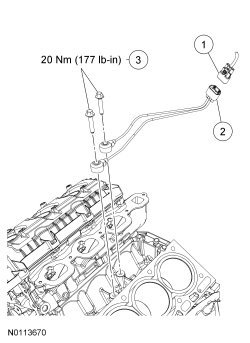
NOTE: It is necessary to remove the lower intake manifold to access the Cylinder Head Temperature (CHT) sensor. For additional information, refer to Engine.
NOTE: LH cylinder head removed in graphic for clarity.

Variable Camshaft Timing (VCT) Oil Control Solenoid
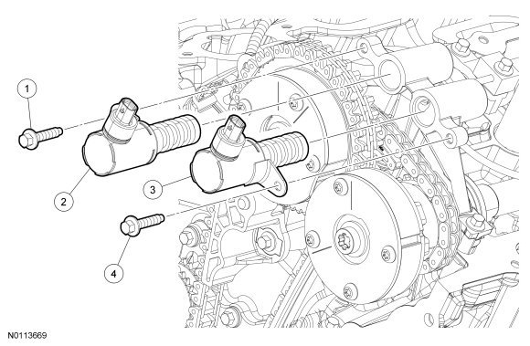
NOTE: It is necessary to remove the RH or LH valve cover to access the Variable Camshaft Timing (VCT) oil control solenoid. For additional information, refer to Engine.
NOTE: Position the VCT (Variable Camshaft Timing) oil control solenoid and tighten the bolts in 2 stages.
- Stage 1: Tighten to 8 Nm (71 lb-in).
- Stage 2: Tighten an additional 20 degrees.
NOTE: LH shown, RH similar.
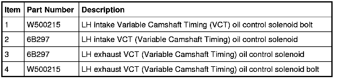
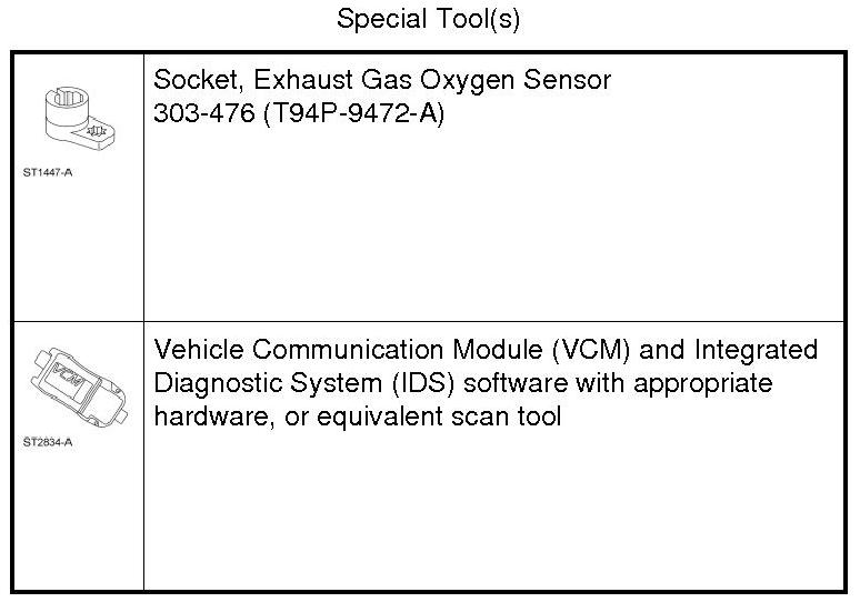
1. Refer to the procedures and/or exploded views for any Warnings, Notices, Notes, Materials, Specifications, and Special Tools. Items in the exploded views may not be listed in order of removal.
Factory Service Tools
Use the Manual With the Right Hardware
Pair factory procedures with proven DIY tools so the instructions are easier to execute.
Disclosure: Verified tool recommendations may earn an affiliate commission at no cost to you.
When to See a Mechanic
Stop DIY work and contact a certified mechanic immediately if any of the following apply:
- • You smell fuel, burning insulation, or see smoke.
- • Brakes feel soft, pull hard to one side, or make grinding noises.
- • The engine overheats, stalls repeatedly, or misfires under load.
- • You are missing required tools, torque specs, or safe lifting equipment.
- • You are not confident in the next step or safety outcome.