
Safety Warning
DIY auto repair can cause serious injury, fire, or vehicle damage. These guides are for informational purposes only. Always follow OEM torque specs, wear PPE, and consult a certified mechanic if you are unsure. You are solely responsible for your safety.
2011 Ford Transit Connect L4-2.0LFACTORY OEM SERVICE PROCEDURE
Frame: Service and Repair
Frame Members
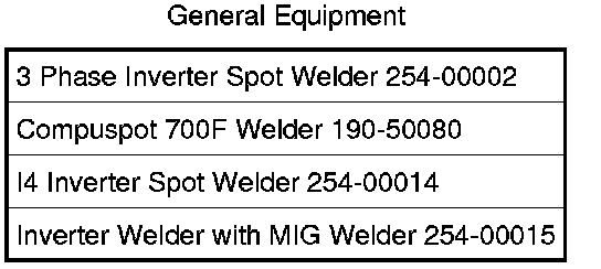
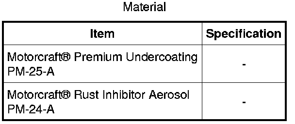
WARNING: Invisible ultraviolet and infrared rays emitted in welding can injure unprotected eyes and skin. Always use protection such as a welder's helmet with dark-colored filter lenses of the correct density. Electric welding will produce intense radiation, therefore, filter plate lenses of the deepest shade providing adequate visibility are recommended. It is strongly recommended that persons working in the weld area wear flash safety goggles. Also wear protective clothing. Failure to follow these instructions may result in serious personal injury.
1. WARNING: Frame rail crush zones absorb crash energy during a collision and must be replaced if damaged. Straighten damaged frame rails to correct frame dimensions prior to frame member sectioning. Failure to follow these instructions may adversely affect frame rail performance and may result in serious personal injury to vehicle occupant(s).
Position the vehicle on a frame repair rack following the manufacturer's recommendations. Measure the vehicle to determine if the body requires rough straightening and alignment. For dimensional information, refer to Body .
2. Remove the hood.
3. Remove the battery. For additional information, refer to Battery, Mounting and Cables Battery.
4. Remove the front bumper cover. For additional information, refer to Bumpers Service and Repair.
5. Remove the fender(s) from the affected side(s). For additional information, refer to Front End Body Panels Fender.
6. Remove the front crossmember assembly.
- Remove the crossmember bolts.
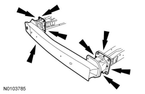
7. Remove the radiator grille opening panel reinforcement. For additional information, refer to Front End Body Panels Radiator Grille Opening Panel Reinforcement.
8. Using a reciprocating saw, plasma cutter or die grinder with a cutting disc, cut through the complete cross section of the outer side member.
- Preliminary outer member cut location
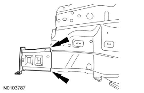
9. Using a reciprocating saw, plasma cutter or die grinder with a cutting disc, cut through the complete cross section of the inner side member.
1. Cut location
2. Drill out the spot welds
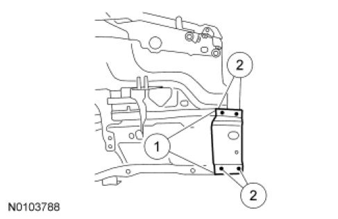
10. Prepare the replacement section of the frame member.
- Cut the replacement section to equal the portion of the original frame member removed.
11. Clamp the service replacement section in position.
- Continuous Metal Inert Gas (MIG) weld the outer frame member
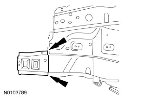
12. Weld the inner portion of the frame member.
1. Continuous MIG weld
2. Resistance spot weld
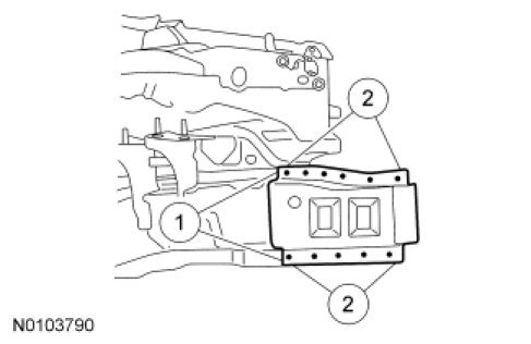
13. Install the crossmember mount bracket.
- Resistance spot weld
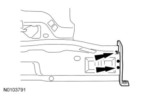
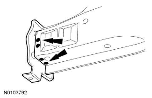
14. Resistance spot weld locations as shown.
15. Install the crossmember.
16. Install the radiator grille opening panel reinforcement. For additional information, refer to Front End Body Panels Radiator Grille Opening Panel Reinforcement.
17. Install the battery. For additional information, refer to Battery, Mounting and Cables Battery.
18. Install the hood.
19. Install the fender(s) from the affected side(s). For additional information, refer to Front End Body Panels Fender.
20. Install the front bumper cover. For additional information, refer to Bumpers Service and Repair.
Removal and Installation
Front Side Member and Fender Apron Panel
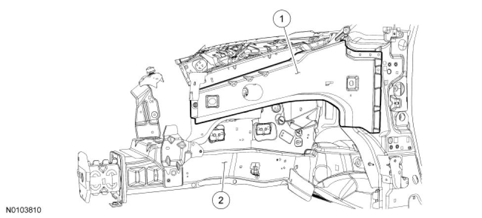
NOTE: Left side shown, right side similar.

WARNING: Invisible ultraviolet and infrared rays emitted in welding can injure unprotected eyes and skin. Always use protection such as a welder's helmet with dark-colored filter lenses of the correct density. Electric welding will produce intense radiation, therefore, filter plate lenses of the deepest shade providing adequate visibility are recommended. It is strongly recommended that persons working in the weld area wear flash safety goggles. Also wear protective clothing. Failure to follow these instructions may result in serious personal injury.
1. WARNING: Frame rail crush zones absorb crash energy during a collision and must be replaced if damaged. Straighten damaged frame rails to correct frame dimensions prior to frame member sectioning. Failure to follow these instructions may adversely affect frame rail performance and may result in serious personal injury to vehicle occupant(s).
Position the vehicle on a frame repair rack following the manufacturer's recommendations. Measure the vehicle to determine if the body requires rough straightening and alignment. For dimensional information, refer to Body .
2. Remove the hood.
3. Remove the fender(s) from the affected side(s). For additional information, refer to Front End Body Panels Fender.
4. Remove the door. For additional information, refer to Body Closures Service and Repair.
5. Remove the cowl panel and body lock carrier.
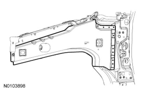
6. Using a reciprocating saw, plasma cutter or die grinder with cutting disc cut the fender apron as indicated.
- Preliminary cut location
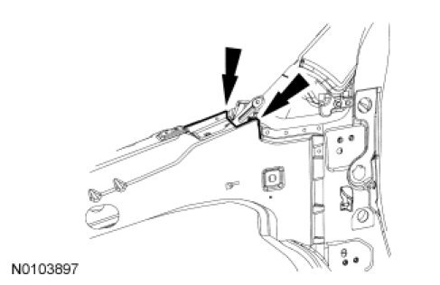
7. Drill out the spot welds.
1. Drill out the spot welds (single panel thickness).
2. Drill out the spot welds (2 panel thicknesses).
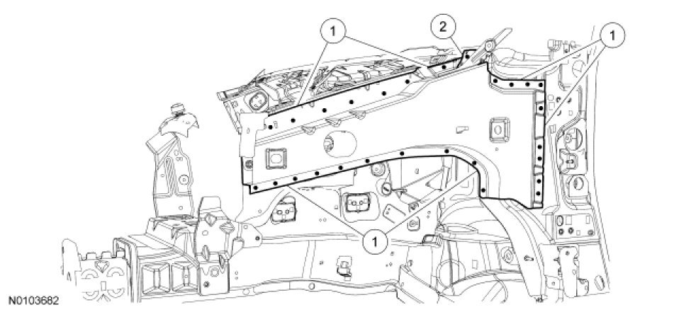
8. Prepare the replacement fender panel for installation.
- Drill 10 mm (0.393 in) diameter holes for puddle welding.
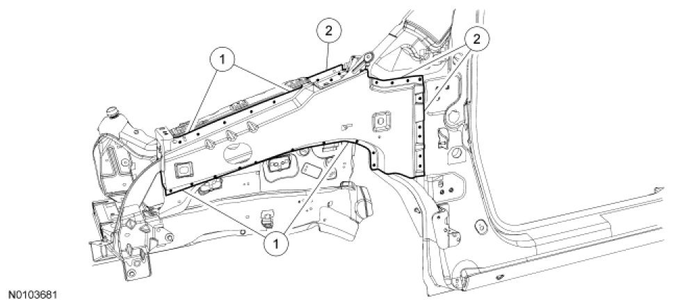
9. Clamp the panel in place and weld.
1. Resistance spot weld
2. Puddle weld
10. Apply corrosion protection to the repair area as required. For additional information, refer to Restoring Corrosion Protection Following Repair .
11. Install the cowl panel and lock carrier.
12. Install the fender(s) from the affected side(s). For additional information, refer to Front End Body Panels Fender.
13. Install the hood.
14. Install the door. For additional information, refer to Body Closures Service and Repair.
Factory Service Tools
Use the Manual With the Right Hardware
Pair factory procedures with proven DIY tools so the instructions are easier to execute.
Disclosure: Verified tool recommendations may earn an affiliate commission at no cost to you.
When to See a Mechanic
Stop DIY work and contact a certified mechanic immediately if any of the following apply:
- • You smell fuel, burning insulation, or see smoke.
- • Brakes feel soft, pull hard to one side, or make grinding noises.
- • The engine overheats, stalls repeatedly, or misfires under load.
- • You are missing required tools, torque specs, or safe lifting equipment.
- • You are not confident in the next step or safety outcome.
Rather have a pro handle this?
A certified mobile mechanic comes to your home or office. They bring the tools, you stay comfortable. No tow truck, no waiting room, no surprises.
Comes to youSame-day available12-month warranty
Get a Free QuoteNo obligation. See pricing before you book.