
Safety Warning
DIY auto repair can cause serious injury, fire, or vehicle damage. These guides are for informational purposes only. Always follow OEM torque specs, wear PPE, and consult a certified mechanic if you are unsure. You are solely responsible for your safety.
2011 Ford Mustang V6-3.7LFACTORY OEM SERVICE PROCEDURE
Subframe - Front
Subframe - Front, 3.7L

Removal and Installation
1. NOTE: Automatic transmission shown, manual transmission similar.
With the vehicle in NEUTRAL, position it on a hoist. For additional information, refer to Jacking and Lifting Service and Repair.
2. Remove the 2 steering column dash boot bearing nuts.

3. NOTE: Use a steering wheel holding device (such as Hunter(R) 28-75-1 or equivalent).
Using a suitable holding device, hold the steering wheel In the straight-ahead position.

4. NOTE: LH shown, RH similar.
If equipped, remove the 4 nuts (2 shown) and the strut tower cross brace.

5. If equipped, detach the 2 retainers and remove the engine appearance cover.
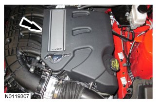
6. NOTE: RH shown, LH similar.
Remove the RH and LH engine mount-to-engine bracket mount nuts.
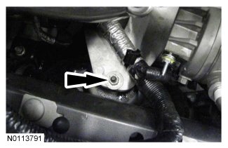
7. Remove the nut from the rear LH valve cover stud bolt and position the generator wiring harness bracket aside.

8. Install the LH engine lift eye.
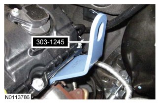
9. Install the RH front engine lift eye.
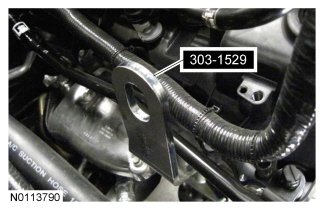
10. Remove the 8 pin-type retainers and the radiator sight shield.

11. Remove the 2 bolts and the RH radiator support bracket.
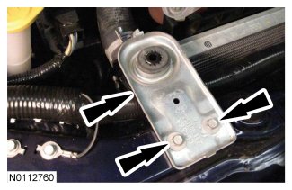
12. NOTICE: Do not position the legs of the Engine Support Bar on the fenders. instead, position the legs on the body structure near the suspension strut tower. Failure to follow these instructions may result in body damage.
Install the Engine Support Bar.

13. Remove the front tires and wheels. For additional information, Refer to Wheels and Tires Removal and Replacement.
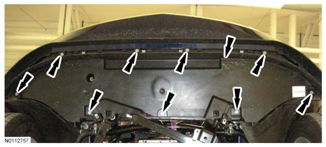
14. Remove the 9 bolts and the lower air deflector.
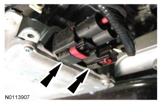
15. NOTICE: The ignition must be off when disconnecting Electronic Power Assist Steering (EPAS) electrical connectors. Failure to follow this direction may lead to DTCs being set in the EPAS module that can not be cleared, and result in the need to install a new EPAS assembly.
Release the 2 red Connector Position Assurance (CPA) features and disconnect the 2 Electronic Power Assist Steering (EPAS) electrical connectors.
- Detach the wiring harness pin-type retainer.
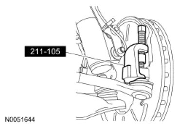
16. Disconnect the outer LH and RH tie-rod ends.
- Remove and discard the tie-rod end nut.
- Using the Tie-Rod End Remover, disconnect the tie-rod end from the wheel knuckle.
17. Disconnect the lower control arm.
- Remove and discard the lower ball joint nut and bolt.
- Separate the lower control arm from the wheel spindle.
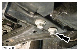
18. NOTE: RH shown, LH similar.
Loosen the 2 nuts for the crossmember brace.
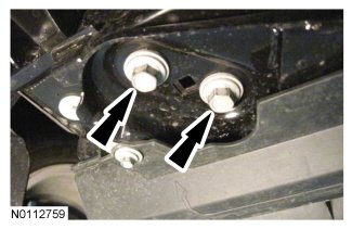
19. NOTE: RH shown, LH similar.
Remove the 6 bolts (2 shown), slide the crossmember forward and remove.
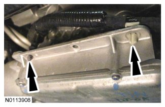
20. Detach the 2 EPAS wiring harness pin-type retainers.
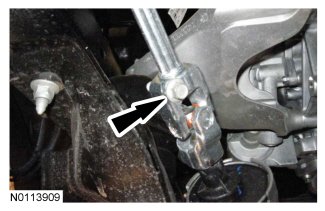
21. Remove the steering shaft pinch bolt and disconnect the steering shaft.
22. Mark the position of the 4 subframe nuts and 4 subframe bolts for reference during installation.
23. NOTE: RH shown, LH similar.
Remove the 4 rear subframe bolts.

24. Position the Powertrain Lift Table under the subframe assembly.

25. NOTE: RH shown, LH similar.
Remove the 4 front subframe nuts.
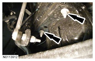
26. Lower the subframe assembly from the vehicle.
Installation
1. If installing a new subframe, transfer the steering rack and lower control arms to the new subframe. For additional information, refer to Power Steering Service and Repair and Front Suspension Front Suspension.
2. Position the subframe to the vehicle and loosely install the 4 front subframe nuts.
3. NOTE: RH shown, LH similar.
Loosely install the 4 rear subframe bolts.
4. Use a suitable alignment tool with a 15 mm (0.59 in) OD shaft that is long enough to go through the subframe and body.
- Align the subframe to the alignment marks made during installation.
5. Tighten the 4 rear subframe bolts to 115 Nm (85 lb-ft).
6. Tighten the 4 front subframe nuts to 115 Nm (85 lb-ft).
7. Remove the Powertrain Lift Table or suitable device from the subframe.
8. Connect the lower control arms to the wheel spindles.
- Install new fasteners.
- Tighten to 115 Nm (85 lb-ft).
9. Connect the outer LH and RH tie-rod ends.
- Install new fasteners.
- Tighten to 80 Nm (59 lb-ft).
10. Connect the steering shaft and install the steering shaft pinch bolt.
- Tighten to 47 Nm (35 lb-ft).
11. Attach the 2 EPAS wiring harness pin-type retainers.
12. NOTE: RH shown, LH similar.
Install the crossmember brace and 6 bolts (2 shown).
- Tighten to 65 Nm (48 lb-ft).
13. NOTE: RH shown, LH similar.
Tighten the 2 nuts for the crossmember brace to 65 Nm (48 lb-ft).
14. NOTE: Make sure the Electronic Power Assist Steering (EPAS) electrical connectors are fully seated and the Connector Position Assurance (CPA) features are engaged.
Connect the 2 Electronic Power Assist Steering (EPAS) electrical connectors and secure the 2 red Connector Position Assurance (CPA) features.
- Attach the wiring harness pin-type retainer.
15. Install the lower air deflector and the 9 bolts.
- Tighten to 5 Nm (44 lb-in).
16. Install the front tires and wheels. For additional information, refer to Wheels and Tires Removal and Replacement.
17. Remove the engine support bar.
18. Remove the LH engine lifting eye and position the generator wiring harness bracket on the rear LH valve cover stud bolt and install the nut.
- Tighten to 10 Nm (89 lb-in).
19. Remove the RH engine lifting eye.
20. Install the RH radiator support bracket and the 2 bolts.
- Tighten to 10 Nm (89 lb-in).
21. Install the radiator sight shield and the 8 pin-type retainers.
22. NOTE: RH shown, LH similar.
Install the RH and LH engine mount bracket-to-engine mount nuts.
- Tighten to 63 Nm (46 lb-ft).
23. If equipped, install the appearance cover.
24. NOTE: LH shown, RH similar.
If equipped, install the strut tower cross brace and the 4 nuts (2 shown)
- Tighten to 35 Nm (26 lb-ft).
25. Install the 2 steering column dash boot bearing nuts.
- Tighten to 9 Nm (80 lb-in).
Factory Service Tools
Use the Manual With the Right Hardware
Pair factory procedures with proven DIY tools so the instructions are easier to execute.
Disclosure: Verified tool recommendations may earn an affiliate commission at no cost to you.
When to See a Mechanic
Stop DIY work and contact a certified mechanic immediately if any of the following apply:
- • You smell fuel, burning insulation, or see smoke.
- • Brakes feel soft, pull hard to one side, or make grinding noises.
- • The engine overheats, stalls repeatedly, or misfires under load.
- • You are missing required tools, torque specs, or safe lifting equipment.
- • You are not confident in the next step or safety outcome.
Rather have a pro handle this?
A certified mobile mechanic comes to your home or office. They bring the tools, you stay comfortable. No tow truck, no waiting room, no surprises.
Comes to youSame-day available12-month warranty
Get a Free QuoteNo obligation. See pricing before you book.