
Safety Warning
DIY auto repair can cause serious injury, fire, or vehicle damage. These guides are for informational purposes only. Always follow OEM torque specs, wear PPE, and consult a certified mechanic if you are unsure. You are solely responsible for your safety.
2011 Ford Explorer FWD V6-3.5LFACTORY OEM SERVICE PROCEDURE
Front Subframe: Service and Repair
Subframe - Front
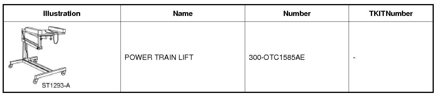
Special Tool(s)
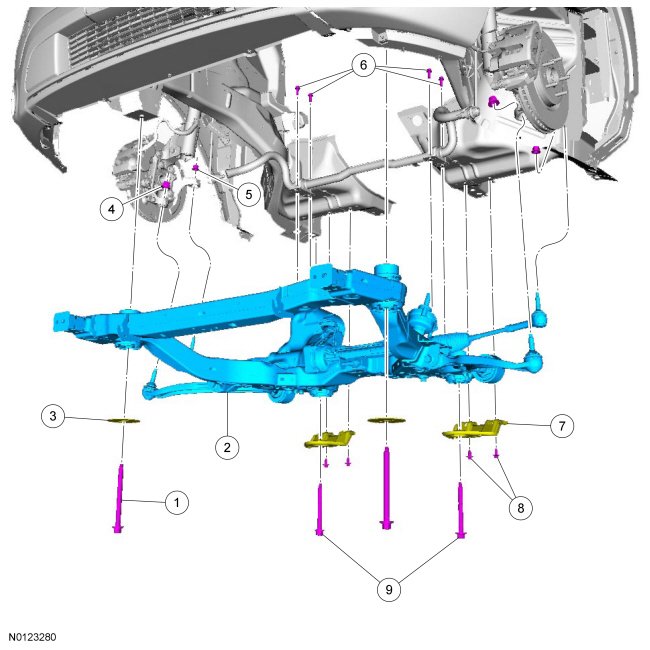
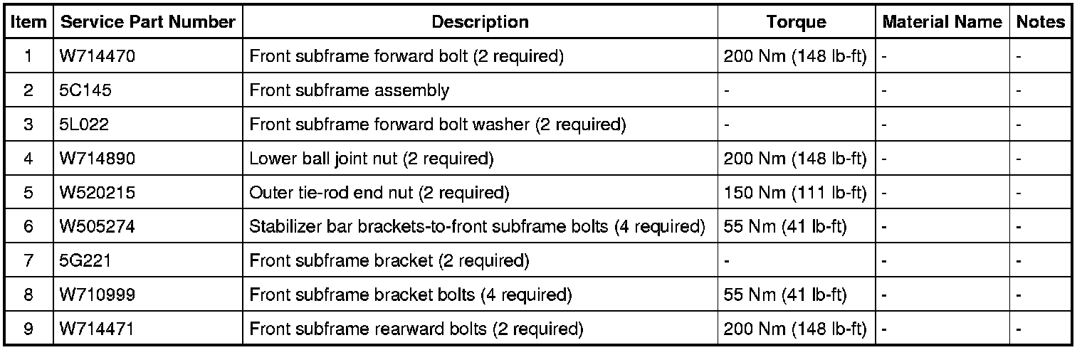
Exploded View
Removal
NOTICE: Suspension fasteners are critical parts that affect performance of vital components and systems. Failure of these fasteners may result in major service expense. Use the same or equivalent parts if replacement is necessary. Do not use a replacement part of lesser quality or substitute design. Tighten fasteners as specified.
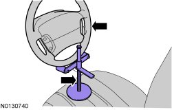
1. NOTE: Use a steering wheel holding device (such as Hunter(R) 28-75-1 or equivalent).
Using a suitable holding device, hold the steering wheel in the straight-ahead position.
2. Remove the wheels and tires. REFER to Wheel and Tire Removal and Replacement.
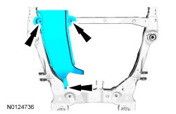
3. If equipped, remove the 3 retainers and the underbody air duct.
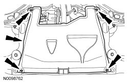
4. If equipped, remove the 4 retainers and the underbody shield.
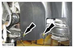
5. NOTE: RH (Right Hand) shown, LH (Left Hand) similar.
Remove the 2 RH (Right Hand) and 2 LH (Left Hand) lower pin-type retainers from the engine splash shields and position the shields aside.
6. Remove the engine exhaust Y-pipe. REFER to Exhaust Y-Pipe Exhaust Y-Pipe.
7. Remove and discard the 4 stabilizer bar bracket-to-front subframe bolts.
8. NOTE: The hex-holding feature can be used to prevent turning of the stud while removing the outer tie-rod end nuts.
NOTE: RH (Right Hand) shown, LH (Left Hand) similar.
Remove and discard both outer tie-rod end nuts.
- Separate both outer tie-rod ends from the wheel knuckles.
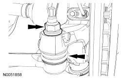
9. NOTICE: Use care when releasing the lower arm and knuckle into the resting position or damage to the ball joint seal or CV (Constant Velocity) boot may occur.
NOTE: Use the hex-holding feature to prevent the stud from turning while removing the lower ball joint nuts.
NOTE: RH (Right Hand) shown, LH (Left Hand) similar.
Remove and discard both lower ball joint nuts.
- Separate both lower ball joints from the wheel knuckles.
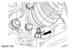
10. Remove the flap heat shield bolt and position the flap heat shield to access the EPAS (Electronic Power Assist Steering) electrical connectors.
11. Remove the bolt and disconnect the 2 EPAS (Electronic Power Assist Steering) electrical connectors and the wiring retainer.
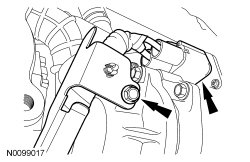
12. NOTICE: Do not allow the steering column to rotate while the steering column shaft is disconnected from the steering gear or damage to the clockspring may occur. If there is evidence that the steering column has rotated, the clockspring must be removed and recentered. REFER to Clockspring Service and Repair.
Remove and discard the steering column shaft bolt and disconnect the steering column shaft from the steering gear.
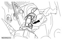
13. NOTE: FWD (Front Wheel Drive) shown, AWD (All-Wheel Drive) Similar.
Remove the roll restrictor-to-subframe bolt.
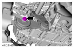
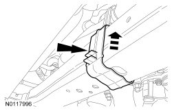
14. Unlatch the cooler hose retainer latch. Pry up on the oil cooler hose retainer to release the retainer and remove it from the subframe.
15. Using a wax pencil (or equivalent) apply witness marks to the vehicle and subframe to aid in installation.
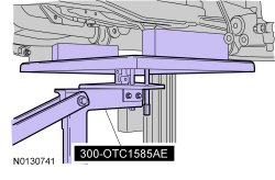
16. Position the 300-OTC1585AE under the subframe assembly.
17. NOTE: RH (Right Hand) shown, LH (Left Hand) similar.
Remove and discard the 4 front subframe bracket bolts.
18. NOTE: RH (Right Hand) shown, LH (Left Hand) similar.
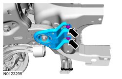
Remove and discard the 2 front subframe rearward bolts and remove the front subframe brackets.
19. NOTE: RH (Right Hand) shown, LH (Left Hand) similar.
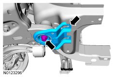
Remove and discard the 2 front subframe forward bolts.
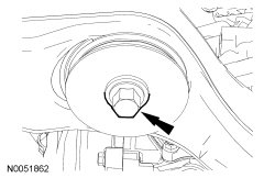
20. Lower the front subframe assembly from the vehicle.
Installation
NOTICE: Suspension fasteners are critical parts that affect performance of vital components and systems. Failure of these fasteners may result in major service expense. Use the same or equivalent parts if replacement is necessary. Do not use a replacement part of lesser quality or substitute design. Tighten fasteners as specified.
1. Using the 300-OTC1585AE , raise and align the subframe assembly to the witness marks made during removal.
2. NOTE: RH (Right Hand) shown, LH (Left Hand) similar.
Install the 2 new front subframe forward bolts.
- Tighten to 200 Nm (148 lb-ft).
3. NOTE: RH (Right Hand) shown, LH (Left Hand) similar.
Position the front subframe brackets and install the 4 new front subframe bracket bolts finger-tight.
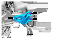
4. NOTE: RH (Right Hand) shown, LH (Left Hand) similar.
Install the 2 new front subframe rearward bolts.
- Tighten to 200 Nm (148 lb-ft).
5. NOTE: RH (Right Hand) shown, LH (Left Hand) similar.
Tighten the 4 new front subframe bracket bolts.
- Tighten to 55 Nm (41 lb-ft).
6. Install the cooler hose retainer on the subframe.
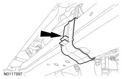
7. NOTE: FWD (Front Wheel Drive) shown, AWD (All-Wheel Drive) similar.
Install the roll restrictor-to-subframe bolt.
- Tighten to 90 Nm (66 lb-ft).
8. NOTICE: Do not allow the steering column to rotate while the steering column shaft is disconnected from the steering gear or damage to the clockspring may occur. If there is evidence that the steering column has rotated, the clockspring must be removed and recentered. REFER to Clockspring Service and Repair.
Install the steering intermediate shaft onto the steering gear and install a new bolt.
- Tighten to 20 Nm (177 lb-in).
9. Connect the 2 EPAS (Electronic Power Assist Steering) electrical connectors and attach the wiring retainer and install the bolt.
- Tighten to 9 Nm (80 lb-in).
10. Position the flap heat shield and install the flap heat shield bolt.
- Tighten to 11 Nm (97 lb-in).
11. NOTE: RH (Right Hand) shown, LH (Left Hand) similar.
Position both ball joints into the wheel knuckles. Install 2 new ball joint nuts.
- Tighten to 200 Nm (148 lb-ft).
12. NOTE: The hex-holding feature can be used to prevent turning of the stud while installing the outer tie-rod nuts.
NOTE: RH (Right Hand) shown, LH (Left Hand) similar.
Position both outer tie-rod ends to the wheel knuckles and install 2 new outer tie-rod end nuts.
- Tighten to 150 Nm (111 lb-ft).
13. Install the 4 new stabilizer bar bracket-to-front subframe bolts.
- Tighten to 55 Nm (41 lb-ft).
14. Install the engine exhaust Y-pipe. REFER to Exhaust Y-Pipe Exhaust Y-Pipe.
15. NOTE: RH (Right Hand) shown, LH (Left Hand) similar.
Position the RH (Right Hand) and LH (Left Hand) engine splash shields and install the 4 lower pin-type retainers.
16. If equipped, install the underbody shield and the 4 retainers.
17. If equipped, install the underbody air duct and the 3 retainers.
18. Install the wheels and tires. REFER to Wheel and Tire Removal and Replacement.
Factory Service Tools
Use the Manual With the Right Hardware
Pair factory procedures with proven DIY tools so the instructions are easier to execute.
Disclosure: Verified tool recommendations may earn an affiliate commission at no cost to you.
When to See a Mechanic
Stop DIY work and contact a certified mechanic immediately if any of the following apply:
- • You smell fuel, burning insulation, or see smoke.
- • Brakes feel soft, pull hard to one side, or make grinding noises.
- • The engine overheats, stalls repeatedly, or misfires under load.
- • You are missing required tools, torque specs, or safe lifting equipment.
- • You are not confident in the next step or safety outcome.
Rather have a pro handle this?
A certified mobile mechanic comes to your home or office. They bring the tools, you stay comfortable. No tow truck, no waiting room, no surprises.
Comes to youSame-day available12-month warranty
Get a Free QuoteNo obligation. See pricing before you book.