
Safety Warning
DIY auto repair can cause serious injury, fire, or vehicle damage. These guides are for informational purposes only. Always follow OEM torque specs, wear PPE, and consult a certified mechanic if you are unsure. You are solely responsible for your safety.
2010 Ford Edge FWD V6-3.5LFACTORY OEM SERVICE PROCEDURE
Front Subframe: Service and Repair
Subframe - Front
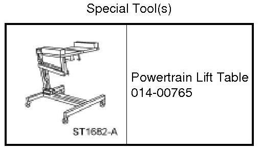
Removal and Installation
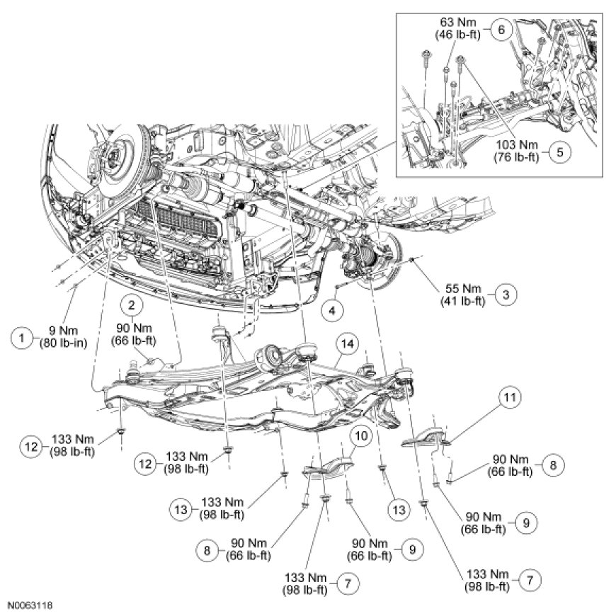
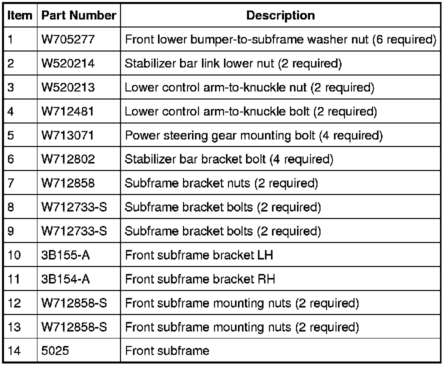
NOTICE: Suspension and subframe fasteners are critical parts because they affect performance of vital parts and systems and their failure may result in major service expense. A new part with the same part number must be installed if installation becomes necessary. Do not use a replacement part of lesser quality or substitute design. Torque values must be used as specified during reassembly to make sure of correct retention of these parts.
1. With a wax pencil, mark the relationship of the front subframe to the underbody at the mounting locations.
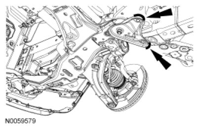
2. Remove the RH splash shield.
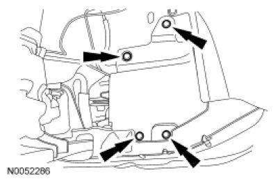
3. Remove the 3 pushpin fasteners, the 7 screws and the front splash shield.
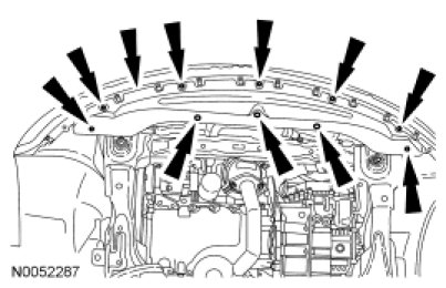
4. Remove the 3 RH subframe-to-lower bumper nuts.
- To install, tighten to 9 Nm (80 lb-in).
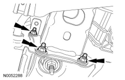
5. Remove the 3 LH subframe-to-lower bumper nuts and separate the lower bumper from the subframe.
- To install, tighten to 9 Nm (80 lb-in).
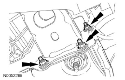
6. Remove the 3 power steering tube bracket bolts from the RH side of the subframe and position the power steering tube aside.
- To install, tighten to 9 Nm (80 lb-in).
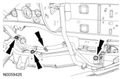
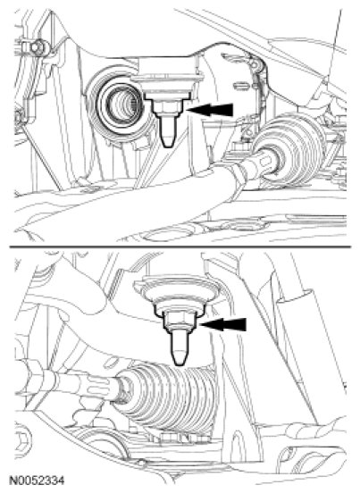
7. NOTE: Use the holding feature to prevent the ball stud from turning while removing or installing the stabilizer bar link nut.
NOTE: RH side shown, LH side similar.
Remove the 2 stabilizer bar link-to-control arm nuts (1 each side) and separate the stabilizer bar links from the lower control arms.
- Discard the nuts.
- To install, tighten to 90 Nm (66 lb-ft).
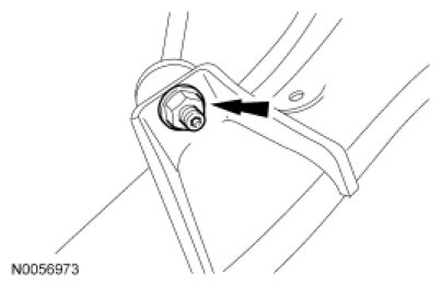
8. NOTE: RH side shown, LH side similar.
Remove the lower control arm-to-knuckle pinch bolts and separate the lower control arms from the knuckles.
- Discard the bolts.
- To install, tighten to 55 Nm (41 lb-ft).
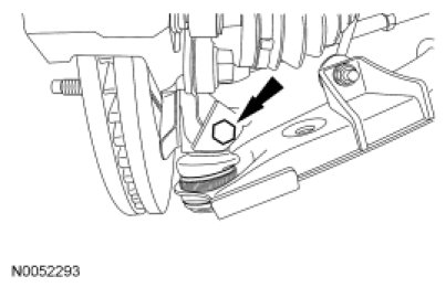
9. Loosen the Y-pipe clamp and disconnect the 2 exhaust hangers.
- To install, tighten to 40 Nm (30 lb-ft).
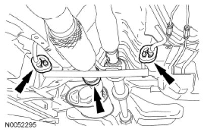
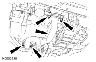
10. Remove the 4 nuts and the Y-pipe assembly.
- To install, tighten to 40 Nm (30 lb-ft).
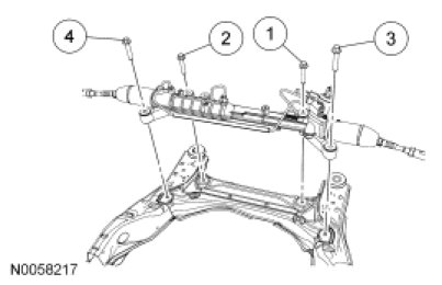
11. NOTE: The steering gear is not removed with the front subframe and must be positioned aside. Position the steering gear aside using mechanic's wire.
Remove the 4 bolts and position the steering rack aside using a suitable length of mechanic's wire.
- Discard the bolts.
- To install, tighten the steering gear bolts in the sequence shown.
- To install, tighten to 103 Nm (76 lb-ft).
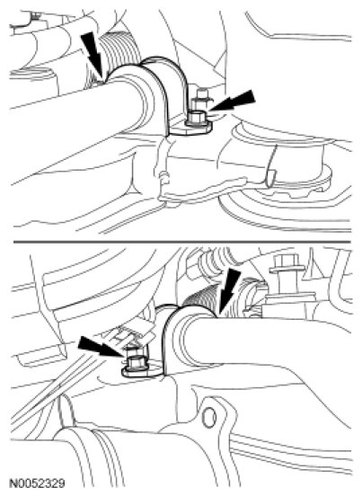
12. Remove the 4 bolts and position the stabilizer bar aside using a suitable length of mechanic's wire.
- Discard the bolts.
- To install, tighten to 63 Nm (46 lb-ft).
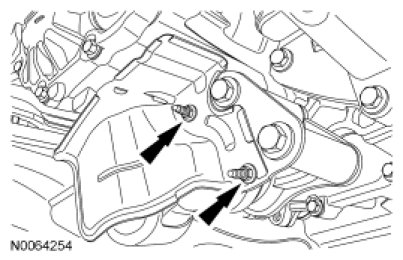
13. Remove the nuts and the roll restrictor heat shield.
- To install, tighten to 11 Nm (97 lb-in).
14. Remove the 3 bolts from the roll restrictor bracket.
- To install, tighten to 90 Nm (66 lb-ft).
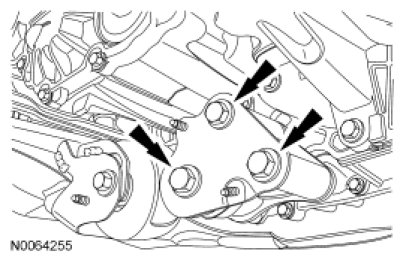
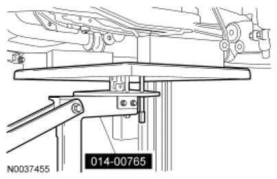
15. Position the lift table under the subframe.
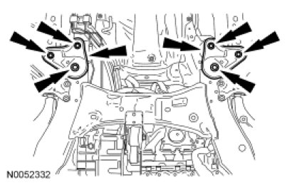
16. NOTE: Align the front subframe index marks to the body index marks made during removal.
NOTE: During installation, the subframe brackets are loosely installed with the support bracket bolts. Tighten the rear subframe nuts prior to tightening the support bracket bolts.
Remove the 2 nuts, 4 bolts and the subframe support brackets.
- Discard the nuts and bolts.
- To install, tighten the nuts to 133 Nm (98 lb-ft).
- To install, tighten the bolts to 90 Nm (66 lb-ft).
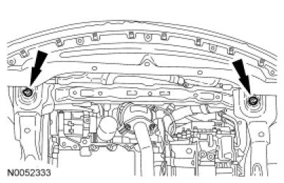
17. Remove the 2 front subframe nuts.
- Discard the nuts.
- To install, tighten to 133 Nm (98 lb-ft).
18. Remove the 2 middle subframe nuts and remove the subframe.
- Discard the nuts.
- To install, tighten to 133 Nm (98 lb-ft).
19. Transfer the components as necessary.
20. To install, reverse the removal procedure.
Factory Service Tools
Use the Manual With the Right Hardware
Pair factory procedures with proven DIY tools so the instructions are easier to execute.
Disclosure: Verified tool recommendations may earn an affiliate commission at no cost to you.
When to See a Mechanic
Stop DIY work and contact a certified mechanic immediately if any of the following apply:
- • You smell fuel, burning insulation, or see smoke.
- • Brakes feel soft, pull hard to one side, or make grinding noises.
- • The engine overheats, stalls repeatedly, or misfires under load.
- • You are missing required tools, torque specs, or safe lifting equipment.
- • You are not confident in the next step or safety outcome.
Rather have a pro handle this?
A certified mobile mechanic comes to your home or office. They bring the tools, you stay comfortable. No tow truck, no waiting room, no surprises.
Comes to youSame-day available12-month warranty
Get a Free QuoteNo obligation. See pricing before you book.