
Safety Warning
DIY auto repair can cause serious injury, fire, or vehicle damage. These guides are for informational purposes only. Always follow OEM torque specs, wear PPE, and consult a certified mechanic if you are unsure. You are solely responsible for your safety.
2008 Ford Fusion FWD L4-2.3LFACTORY OEM SERVICE PROCEDURE
Rear Subframe: Service and Repair
Subframe - Rear
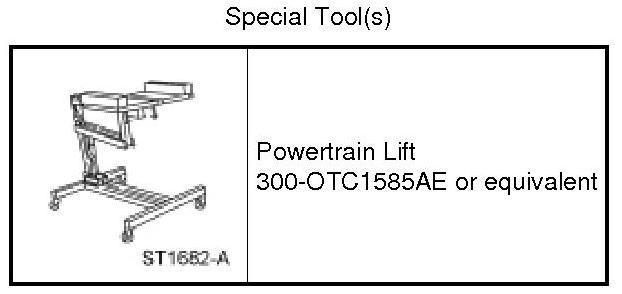
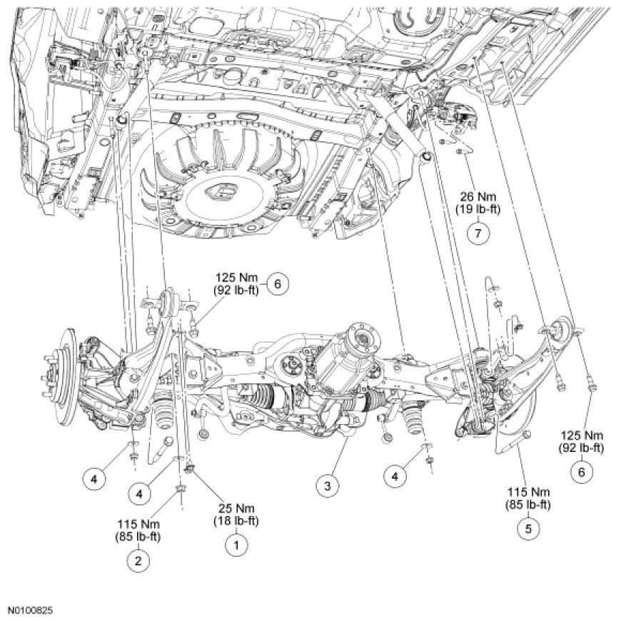
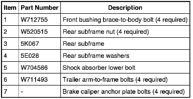
NOTICE: Suspension fasteners are critical parts because they affect performance of vital parts and systems and their failure can result in major service expense. A new part with the same part number must be installed if installation becomes necessary. Do not use a replacement part of lesser quality or substitute design. Torque values must be used as specified during reassembly to make sure of correct retention of these parts.
All vehicles
1. Remove the rear wheels. For additional information, refer to Section 204-04 .
2. With a wax pencil, mark the relationship alignment of the rear subframe to the underbody at the mounting locations.
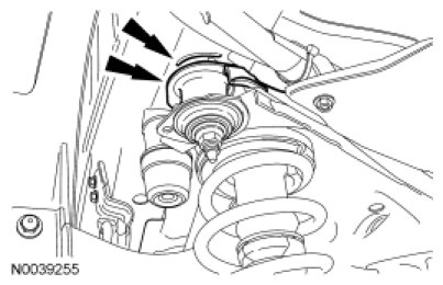
3. Remove the LH and RH rear lower arms. For additional information, refer to Section 204-02 .
4. Remove the catalytic converter, muffler and tailpipe as an assembly.
All-Wheel Drive (AWD) only
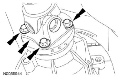
5. NOTE: Index-mark the rear axle pinion flange and the driveshaft yoke.
Remove the 4 driveshaft bolts.
- To install, tighten to 83 Nm (61 lb-ft).
All vehicles
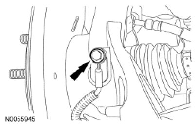
6. Remove the bolt from the LH and RH wheel speed sensors.
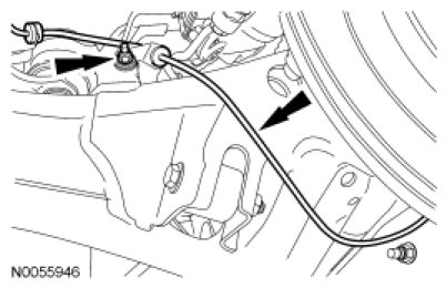
7. Remove the RH and LH wheel speed sensor nuts from the stud and position aside.
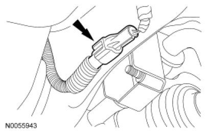
AWD only
8. Disconnect the differential electrical connector on the LH side of the subframe.
All vehicles
9. Remove the 4 bolts (2 each side) from the rear hub spindle-to-brake caliper.
- To install, tighten to 59 Nm (44 lb-ft).
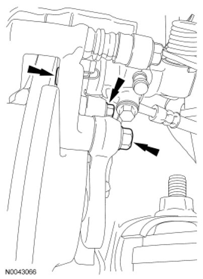
10. Position the brake calipers aside using mechanic's wire. It is not necessary to disconnect the hydraulic brake lines.
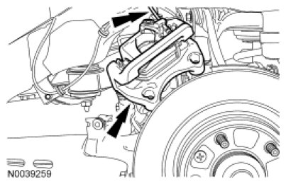
11. Remove the bolts from the parking brake cable-to-trailing link bracket.
- To install, tighten to 22 Nm (16 lb-ft).
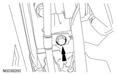
12. Remove and discard the rear shock-to-trailing link lower bolts and flagnuts.
- To install, tighten to 115 Nm (85 lb-ft) with the suspension at the bushing fastener tightening position.
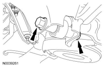
13. Remove the 4 bolts and cone washers (2 each side) from the trailing links-to-vehicle body.
- To install, tighten to 103 Nm (76 lb-ft).
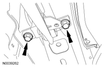
NOTICE: The rear subframe must be secured to the lifting table. The rear subframe can become unstable and fall from the lifting table.
NOTE: For All-Wheel Drive (AWD) vehicles, the rear differential is removed with the rear subframe.
14. Position the Powertrain Lift under the rear subframe.

15. Remove the 4 front (2 each side) bushing brace-to-body bolts.
- To install, tighten to 25 Nm (18 lb-ft).
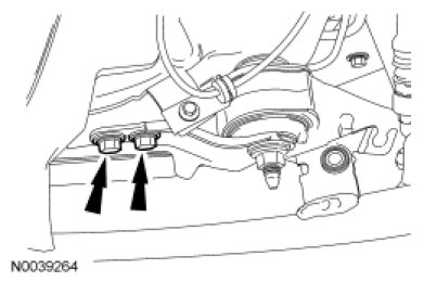
16. Remove the 2 front (1 each side) mounting nuts and washers.
- To install, tighten to 115 Nm (85 lb-ft).
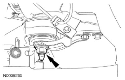
17. Remove the 2 rear mounting nuts.
- To install, tighten to 115 Nm (85 lb-ft).
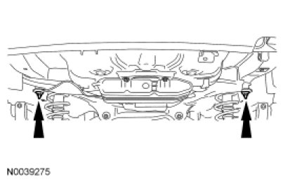
18. Remove the rear subframe.
19. Transfer the components as necessary.
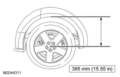
20. NOTE: Make sure the vehicle is at the correct vehicle ride height. For additional information, refer to Section 204-00 .
To install, reverse the removal procedure.
Factory Service Tools
Use the Manual With the Right Hardware
Pair factory procedures with proven DIY tools so the instructions are easier to execute.
Disclosure: Verified tool recommendations may earn an affiliate commission at no cost to you.
When to See a Mechanic
Stop DIY work and contact a certified mechanic immediately if any of the following apply:
- • You smell fuel, burning insulation, or see smoke.
- • Brakes feel soft, pull hard to one side, or make grinding noises.
- • The engine overheats, stalls repeatedly, or misfires under load.
- • You are missing required tools, torque specs, or safe lifting equipment.
- • You are not confident in the next step or safety outcome.