
Safety Warning
DIY auto repair can cause serious injury, fire, or vehicle damage. These guides are for informational purposes only. Always follow OEM torque specs, wear PPE, and consult a certified mechanic if you are unsure. You are solely responsible for your safety.
2008 Ford Fusion FWD L4-2.3LFACTORY OEM SERVICE PROCEDURE
Front Subframe: Service and Repair
Subframe - Front
Removal and Installation
All vehicles
1. With the vehicle in NEUTRAL, position it on a hoist.
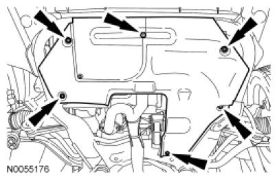
2. NOTE: MKZ shown, all other vehicles similar.
Remove the bolts and the underbody shield, if equipped.
- To install, tighten to 7 Nm (62 lb-in).
Vehicles with 3.0L
3. Remove the exhaust flexible pipe.
4. Remove the 2 bolts and the heat shield.
All vehicles
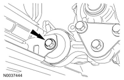
5. Remove the bolt from the engine roll restrictor.
- To install, tighten to 90 Nm (66 lb-ft).
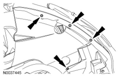
6. Remove the 4 screws and position the RH fender splash shield aside.
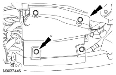
7. Remove the 6 pin-type retainers and the RH front structure-to-subframe splash shield.
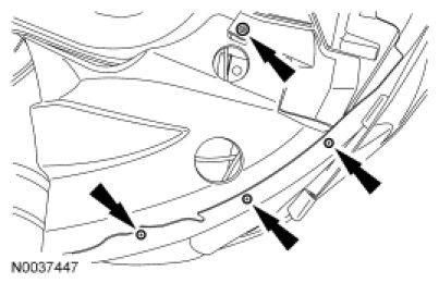
8. Remove the 4 screws and position the LH fender splash shield aside.
9. Remove the 6 pin-type retainers and the LH front structure-to-subframe splash shield.
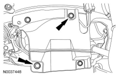
10. Remove the 3 power steering return line bolts.
- To install, tighten to 9 Nm (80 lb-in).
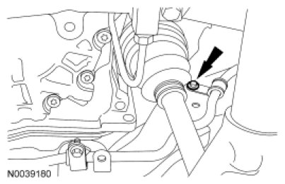
Vehicles with 2.3L
11. Remove the power steering pressure line bracket bolt.
- To install, tighten to 9 Nm (80 lb-in).
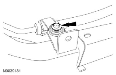
All vehicles
12. Remove the 3 steering gear mounting bolts.
- To install, tighten to 107 Nm (79 lb-ft).
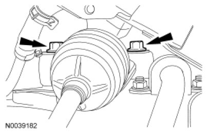
13. NOTE: The steering gear is not removed with the front subframe and must be positioned aside.
Position the steering gear aside using mechanic's wire.
14. Remove the 2 (one each side) lower stabilizer bar link nuts and separate from the stabilizer bar.
- To install, tighten to 42 Nm (31 lb-ft).
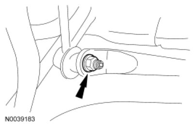
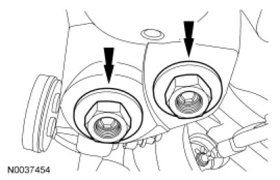
15. Remove the RH and LH lower ball joint nuts.
- To install, tighten to 200 Nm (148 lb-ft).
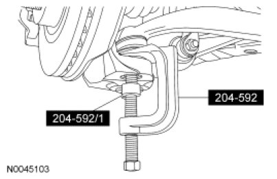
16. NOTICE: When the lower ball joint is separated from the wheel knuckle, the lower arm may strike the outer constant velocity (CV) joint boot with enough force to damage the boot clamp. This will result in a loss of grease from the outer CV joint. Place a block of wood, or similar item, between the lower arm and the outer CV joint to prevent the lower arm from striking the outer CV joint.
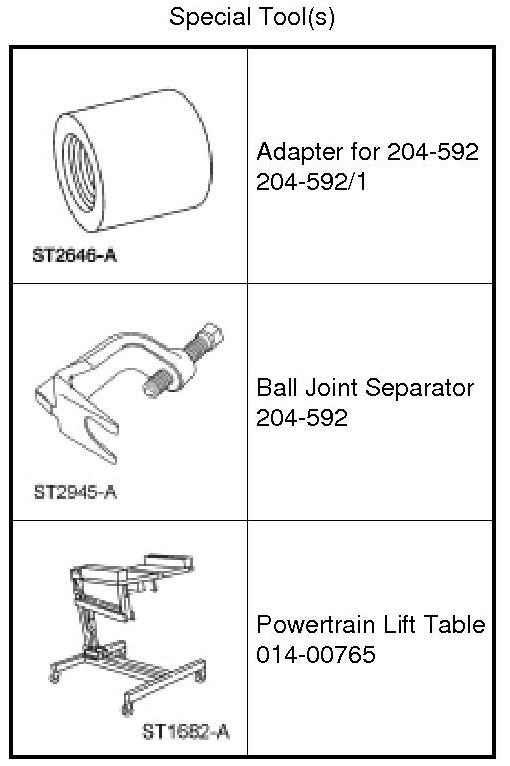
NOTE: Once pressure is applied to the ball joint with the Ball Joint Separator and the Adapter, it may be necessary to tap the wheel knuckle at the ball joint area to separate the ball joint from the wheel knuckle.
Using the Ball Joint Separator and the Adapter, separate the RH and LH ball joints.
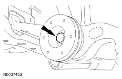
17. Remove the lower control arm-to-strut through bolts and flagnuts.
- To install, tighten to 103 Nm (76 lb-ft).
18. Position the Powertrain Lift Table under the subframe.
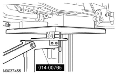
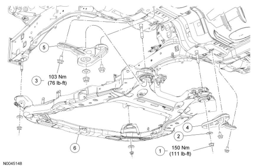
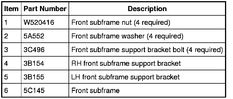
19. Remove the 2 rear mounting nuts and washers from the front subframe.
- To install, tighten to 150 Nm (111 lb-ft).

20. Remove the 4 bolts and the 2 subframe support brackets.
- To install, tighten to 103 Nm (76 lb-ft).
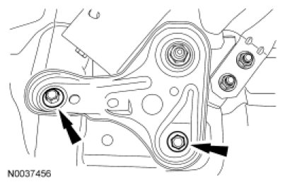
21. Remove the 2 front mounting nuts and washers from the front subframe.
- To install, tighten to 150 Nm (111 lb-ft).
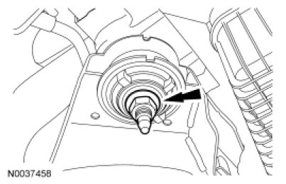
22. Lower the subframe from the vehicle.
- To install, reverse the removal procedure.
Factory Service Tools
Use the Manual With the Right Hardware
Pair factory procedures with proven DIY tools so the instructions are easier to execute.
Disclosure: Verified tool recommendations may earn an affiliate commission at no cost to you.
When to See a Mechanic
Stop DIY work and contact a certified mechanic immediately if any of the following apply:
- • You smell fuel, burning insulation, or see smoke.
- • Brakes feel soft, pull hard to one side, or make grinding noises.
- • The engine overheats, stalls repeatedly, or misfires under load.
- • You are missing required tools, torque specs, or safe lifting equipment.
- • You are not confident in the next step or safety outcome.
Rather have a pro handle this?
A certified mobile mechanic comes to your home or office. They bring the tools, you stay comfortable. No tow truck, no waiting room, no surprises.
Comes to youSame-day available12-month warranty
Get a Free QuoteNo obligation. See pricing before you book.