
Safety Warning
DIY auto repair can cause serious injury, fire, or vehicle damage. These guides are for informational purposes only. Always follow OEM torque specs, wear PPE, and consult a certified mechanic if you are unsure. You are solely responsible for your safety.
2008 Ford Focus L4-2.0LFACTORY OEM SERVICE PROCEDURE
Front Subframe: Service and Repair
SUBFRAME - FRONT
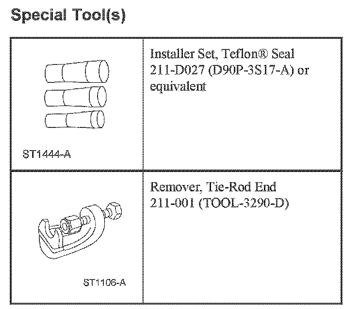
Special Tool(s):
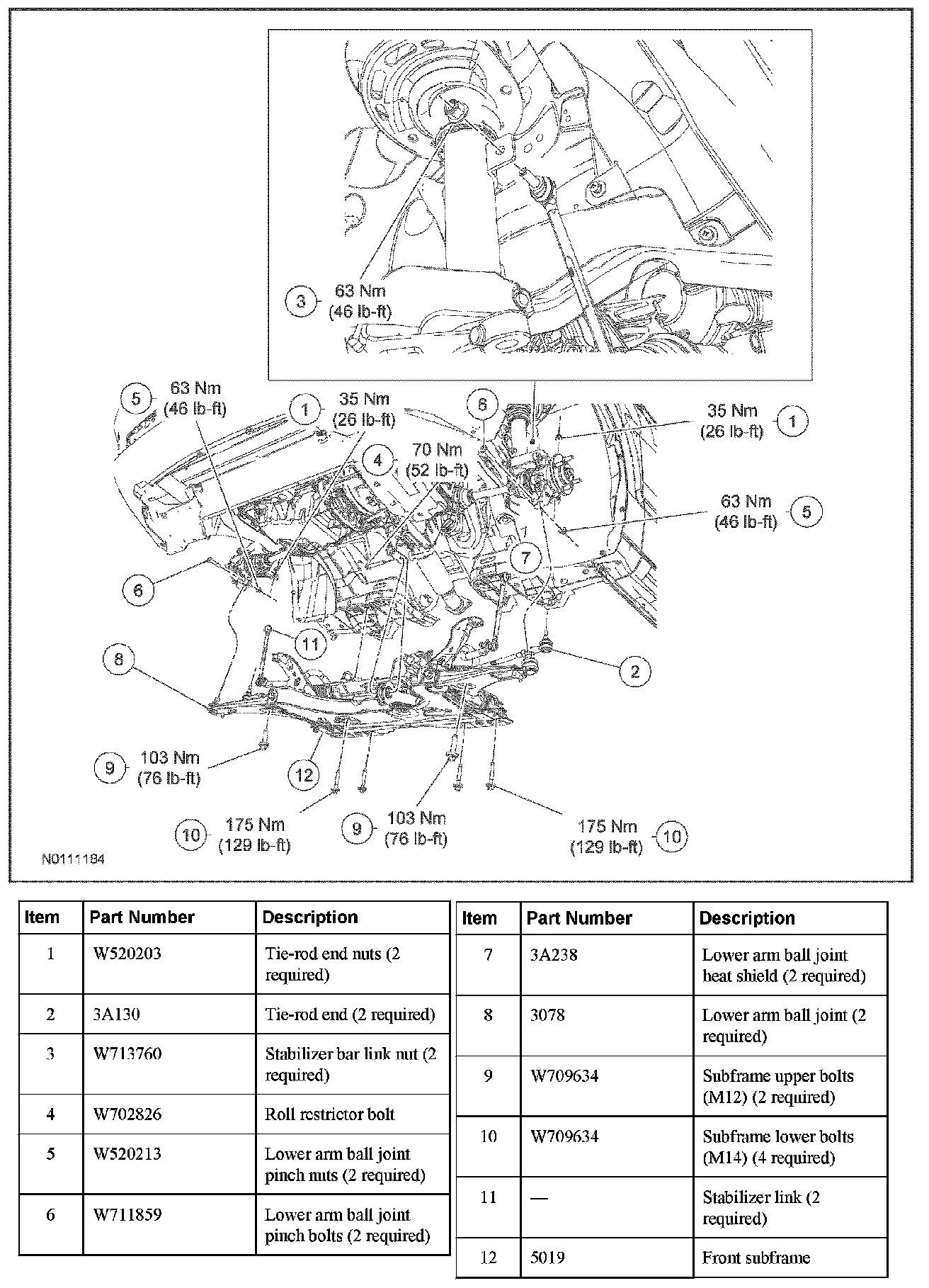
NOTE: The front bumper cover and the RH/LH brake assemblies have been removed for clarity.
Removal
1. Center the steering wheel, remove the ignition key and lock the steering wheel in position.
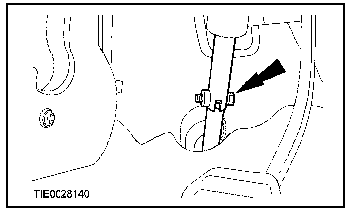
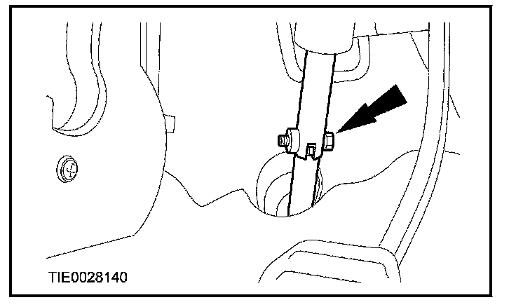
2. Disconnect the steering column shaft from the steering column coupling shaft.
- Discard the bolt.
3. Remove the front wheels and tires.
4. NOTICE: Leave the tie-rod end nuts in place to protect the ball joint studs or damage to the vehicle may occur.
Loosen the tie-rod end nut on both sides.
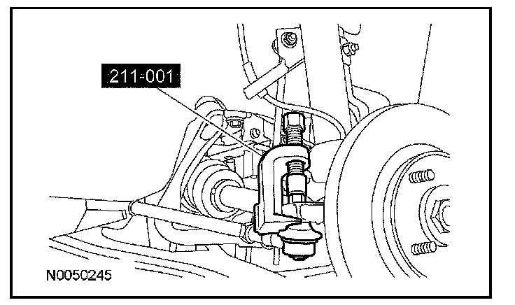
5. Using the Tie-Rod End Remover, disconnect the tie-rod end from the wheel knuckle on both sides.
- Remove and discard the tie-rod end nuts.
6. Remove the stabilizer bar link nuts on both sides.
7. Remove the engine support insulator-to-transaxle center bolt.
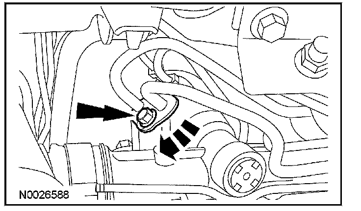
8. Remove the power steering line retainer bolt from the steering gear.
9. Remove the power steering lines bolt, rotate the power steering line clamp clockwise, and disconnect the 2 power steering lines from the power steering gear.
- Allow the remaining oil to drain into a suitable container.
- Discard the O-ring seals.
10. Remove the roll restrictor bolt.
11. Using a suitable support table, support the front subframe.
12. Index-mark the location of the subframe to the vehicle before removal.
13. NOTE: Separate the ball joint from the wheel knuckle as the front subframe is lowered.
Disconnect the lower arm ball joint from the wheel knuckle on both sides.
- Remove the 2 lower arm ball joint heat shields.
14. Remove the 6 subframe bolts.
15. Remove the front subframe.
16. If installing a new front subframe, transfer parts as necessary.
Installation
1. Position the subframe to the vehicle.
2. NOTE: While tightening the subframe bolts, make sure the front subframe does not move.
Loosely install the 4 subframe lower bolts.
- Align the index marks made before removal.
- Tighten to 175 Nm (129 lb-ft).
3. Install the 2 subframe upper bolts.
- Tighten to 103 Nm (76 lb-ft).
4. Install the roll restrictor bolt.
- Tighten to 70 Nm (52 lb-ft).
5. Remove the support table.
6. NOTICE: Make sure the 2 lower arm ball joint heat shields are installed to prevent damage to the ball joints.
Install the 2 heat shields (1 each side).
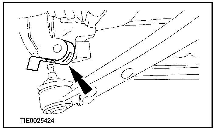
7. Position the lower arm ball joint to the wheel knuckle on both sides and install the bolts and nuts.
- Tighten to 63 Nm (46 lb-ft).
8. NOTE: New O-ring seals must be installed any time the lines are disconnected from the steering gear.
Using the Teflon(R) Seal Installer Set, install new O-ring seals (high-pressure hose pin, 3F886-AA, return hose pin 3F886-BA) onto the power steering lines.
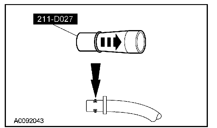
9. Connect the power steering lines to the power steering gear, rotate the power steering line clamp counterclockwise and install the bolt.
- Tighten to 18 Nm (159 lb-in).
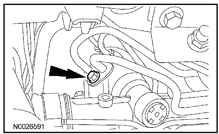
10. Install the power steering line retainer bolt.
11. Install the engine support insulator-to-transaxle center bolt.
- Tighten to 50 Nm (37 lb-ft).
12. Install the 2 stabilizer bar links and the nuts.
- Tighten to 63 Nm (46 lb-ft).
13. WARNING: Do not reuse a tie rod-to-wheel knuckle nut. This can result in nut failure and loss of steering control. Failure to follow this instruction may result in serious injury to vehicle occupant(s).
Install the 2 tie-rod ends and the nuts.
- Tighten to 35 Nm (26 lb-ft).
14. Install the front wheels and tires.
15. WARNING: Install a new steering column shaft bolt. Reuse could result in bolt failure and loss of vehicle control. Failure to follow this instruction may result in serious injury to vehicle occupant(s).
Connect the steering column shaft to the steering column coupling shaft and install the bolt.
- Tighten to 28 Nm (21 lb-ft).
16. Fill and bleed the power steering system.
17. Check the front end alignment and adjust as necessary.
Factory Service Tools
Use the Manual With the Right Hardware
Pair factory procedures with proven DIY tools so the instructions are easier to execute.
Disclosure: Verified tool recommendations may earn an affiliate commission at no cost to you.
When to See a Mechanic
Stop DIY work and contact a certified mechanic immediately if any of the following apply:
- • You smell fuel, burning insulation, or see smoke.
- • Brakes feel soft, pull hard to one side, or make grinding noises.
- • The engine overheats, stalls repeatedly, or misfires under load.
- • You are missing required tools, torque specs, or safe lifting equipment.
- • You are not confident in the next step or safety outcome.
Rather have a pro handle this?
A certified mobile mechanic comes to your home or office. They bring the tools, you stay comfortable. No tow truck, no waiting room, no surprises.
Comes to youSame-day available12-month warranty
Get a Free QuoteNo obligation. See pricing before you book.