
Safety Warning
DIY auto repair can cause serious injury, fire, or vehicle damage. These guides are for informational purposes only. Always follow OEM torque specs, wear PPE, and consult a certified mechanic if you are unsure. You are solely responsible for your safety.
1992 Ford Mustang L4-140 2.3L SOHCFACTORY OEM SERVICE PROCEDURE
Assembly
Transmission
1. Using a press, install front countershaft bearing onto countershaft using Bearing Installation Tool T57L-4621-B or equivalent.
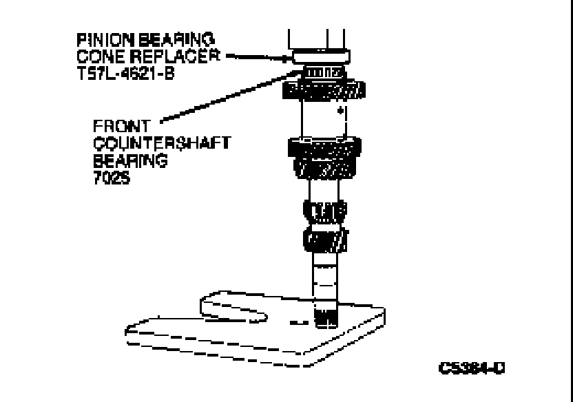
2. Position countershaft in case.

3. Using a press and Bearing Installer T83P-7025-AH or equivalent, install countershaft rear bearing to countershaft.
NOTE:Support the countershaft cluster gear using two pieces of 7mm (1/4-inch) bar stock.
CAUTION:Failure to properly support the countershaft cluster gear can result in permanent distortion of the case during bearing installation.

4. Install rear countershaft bearing race onto countershaft.
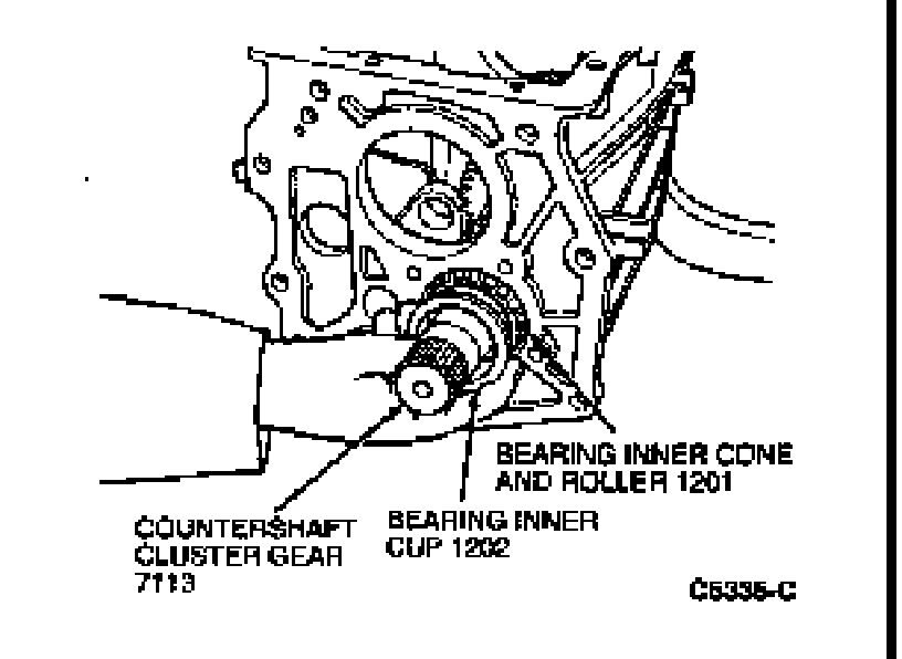
5. Install countershaft retainer to transmission housing with four 13mm bolts.
NOTE:This should be done initially without any shims installed. Tighten bolts to 15-27 Nm (11-20 lb-ft).
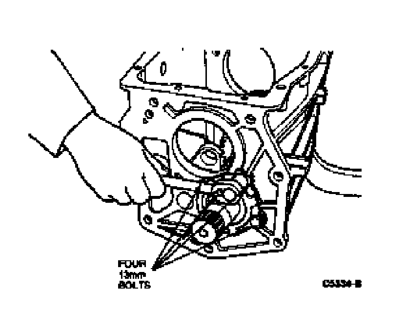
6. Measure end play using Universal Dial Indicator D78P-4201-G and Bracketry D78P-4201-F, or equivalent.
Remove retainer and install necessary shim(s) between countershaft retainer and rear countershaft bearing race. Verify end play is within 0.0254-0.127mm (0.001-0.005 inch). After installing countershaft rear bearing retainer, bend tabs on countershaft rear bearing retainer over the four retaining bolts.
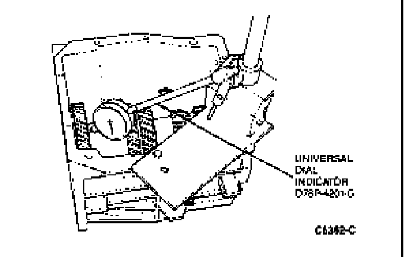
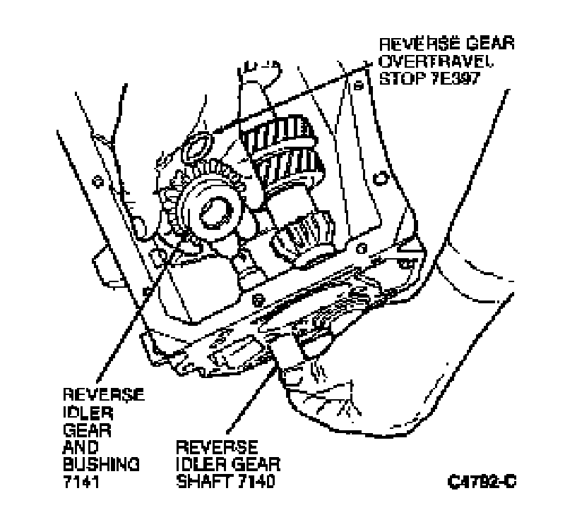
7. Position reverse idler gear in case with shift lever groove facing rear of case.
Install reverse idler gear shaft and rubber overtravel stop. Install shaft from rear of case and position overtravel stop between gear and bushing and shaft support.
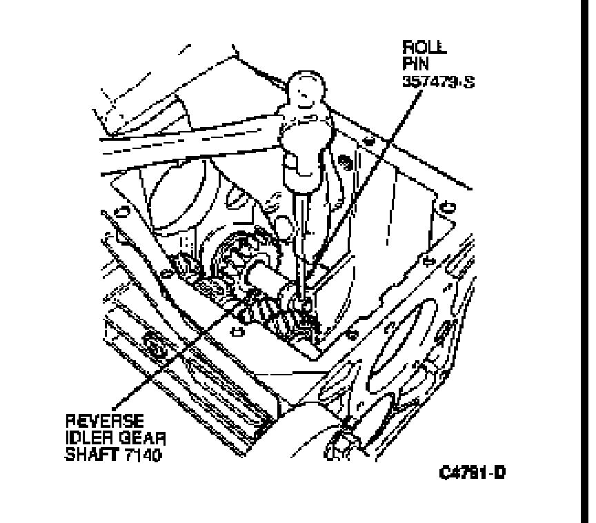
8. Using a 5mm (3/16-inch) pin punch, install reverse idler gear shaft roll pin.
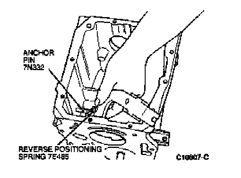
9. If removed, apply Pipe Sealant with Teflon D8AZ-19554-A (ESG-M4G194-A) or equivalent to inhibitor spring pin threads. Install anchor pin and tighten to 8-15 Nm (6-11 lb-ft).
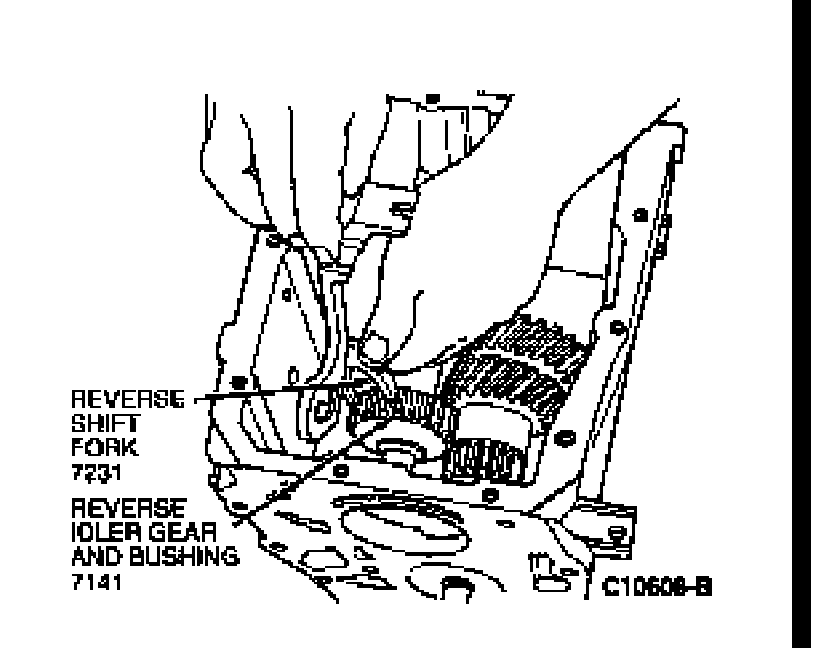
10. Align fifth/reverse shift lever, reverse shift fork and reverse positioning/inhibitor spring as shown.
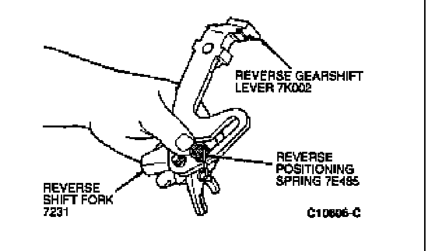
11. Lower assembly into case and install looped end of reverse positioning/inhibitor spring onto anchor pin.
12. Position reverse idler gear into the NEUTRAL position and align reverse shift fork onto reverse idler gear. Once aligned, push downward on shift fork until fully engaged into reverse idler gear.
NOTE:Observe reverse positioning/inhibitor spring rotation. Reverse positioning spring should rotate counterclockwise into its installed position.
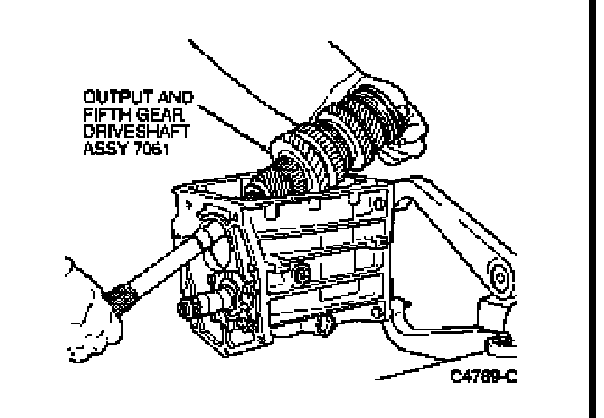
13. Install output shaft assembly.
14. Coat the 15 input shaft roller bearings, thrust bearing and race with Multi-Purpose Grease D0AZ-19584-AA (ESR-M1C159-A) or equivalent. Install components in input shaft.

15. Align notches in blocking ring with inserts in 3-4 synchronizer and install synchronizer blocking ring .
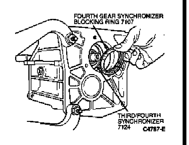
16. Install input shaft. Align flat on synchronizer teeth with countershaft before installing input shaft.
NOTE:Ensure three/four synchronizer blocking ring is still in proper position.

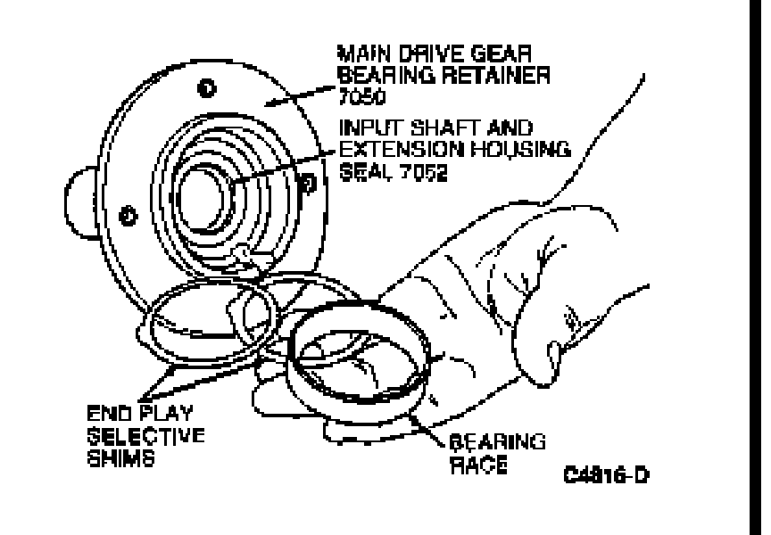
17. Install bearing race in bearing retainer.
NOTE:Do not install end play shims at this point.
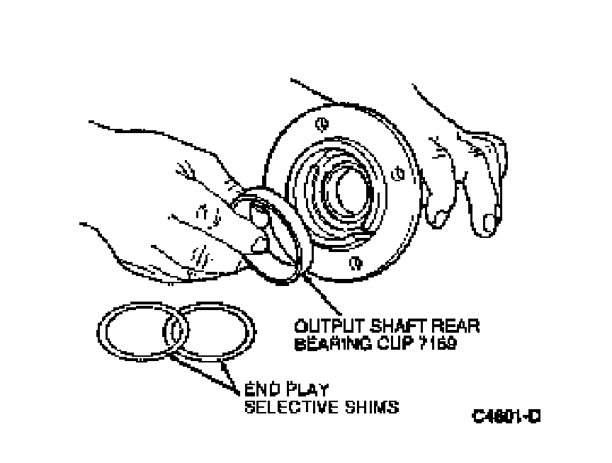
18. Temporarily, install bearing retainer with narrow or smaller notch facing upward. Do not apply sealant to the main drive gear bearing retainer at this point.
19. Tighten retaining bolts to 15-27 Nm (11-20 lb-ft).
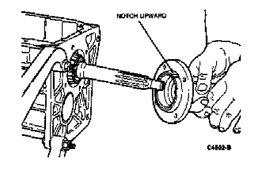
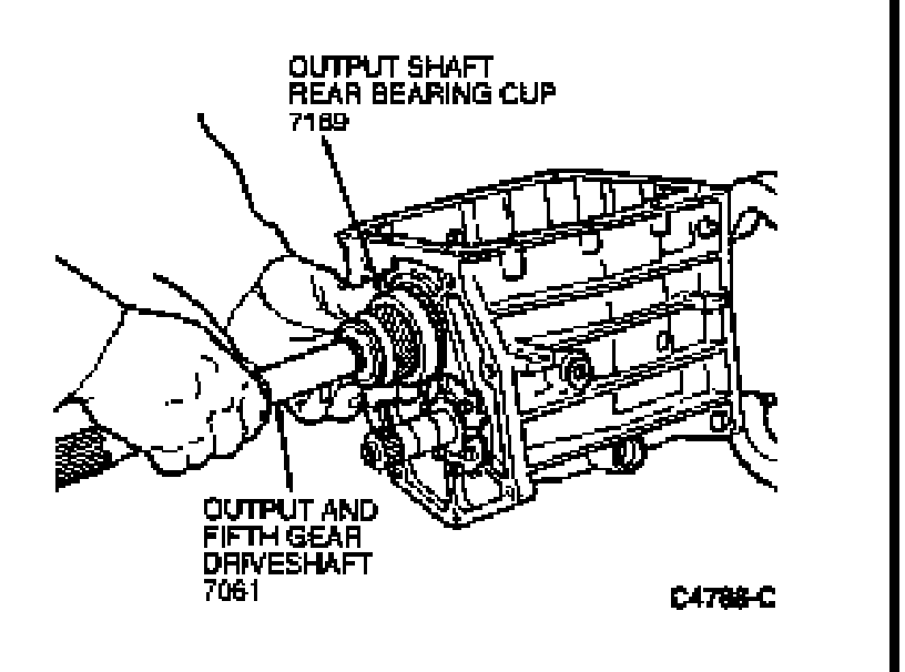
20. Install output shaft rear bearing race. If necessary, tap bearing race into position using a plastic-tipped hammer.
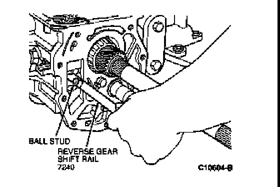
21. Install fifth/reverse shift rail into transmission case by aligning ball stud with slot in case and aligning shift rail with reverse shift fork. Once ball stud enters case, rotate shift rail clockwise and push in shift rail until ball aligns with fifth/reverse shift lever . Rotate shift rail counterclockwise until ball stud fully engages shift lever.
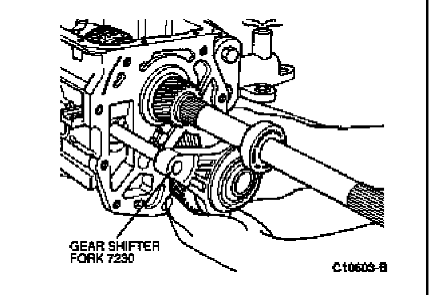
22. Install fifth gear, synchronizer and shifter fork as an assembly.
23. Install synchronizer blocking ring, brake ring, retainer and fifth gear synchronizer snap ring.
NOTE:Ensure tabs on retainer engage splines of counter shaft.
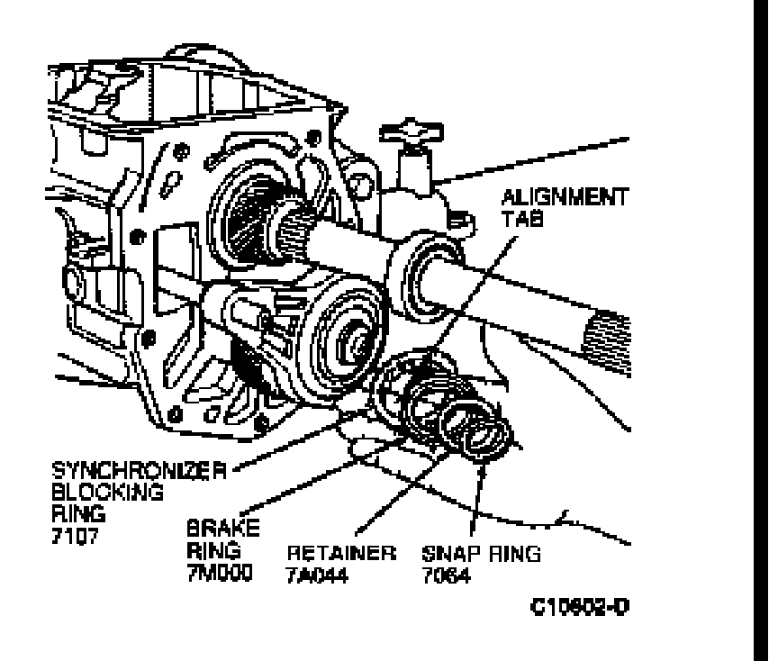
24. Apply Pipe Sealant with Teflon� D8AZ-19554-A (ESG-M4G194-A) or equivalent to the pivot pin threads and install the fifth/reverse shift lever pivot pin.
NOTE:Before installing the pivot pin, ensure the shift rail ball stud is fully engaged with the shift lever.
Tighten pivot pin to 34-47 Nm (25-35 lb-ft) using a T55 Torx� driver. Apply Pipe Sealant with Teflon� D8AZ-19554-A (ESG-M4G194-A) or equivalent to the backup lamp switch and install using a 22mm socket. Tighten to 27-47 Nm (20-35 lb-ft).

25. Using needlenose pliers, install C - clip on shift lever pivot pin.
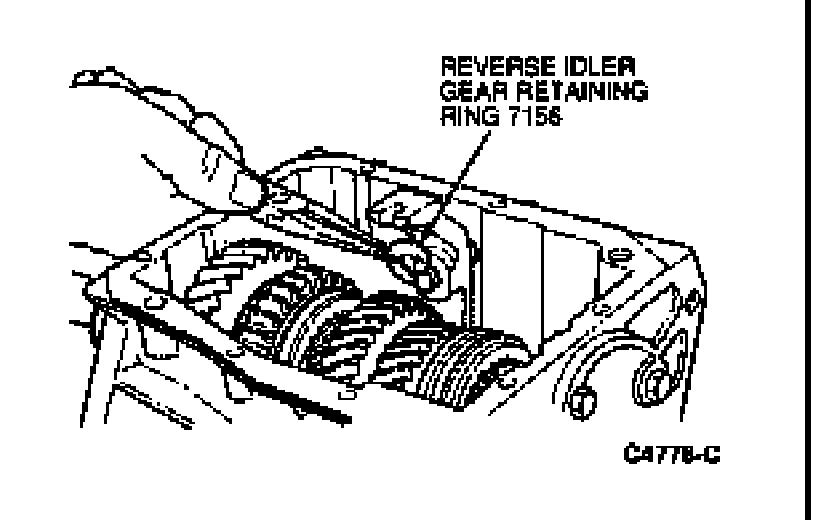
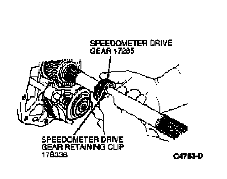
26. Install speedometer drive gear (17285).
NOTE:The tab on the retainer clip engages a hole in the output shaft.
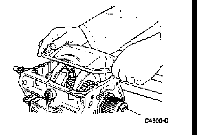
27. Apply 3.2mm (1/8 inch) bead of Silicone Rubber D6AZ-19562-AA or BA (ESB-M4G92-A) or equivalent shift cover assembly.
CAUTION: Do not apply silicone sealer to top of transmission case surface under any circumstances, as sealant could fall into transmission and affect operation.
Position case cover to filler plug side of transmission and lower into position until shift forks engage synchronizers . Continue lowering case cover and move into position to engage fifth/reverse shift lever.
NOTE:Ensure all synchronizers are in the NEUTRAL position and that the shifter forks in the case cover are in the NEUTRAL position.
28. Install case cover retaining bolts. Tighten case cover retaining bolts to 8-15 Nm (6-11 lb-ft).
29. Apply a 3.2mm (1/8-inch) bead of Silicone Rubber D6AZ-19562-AA or BA (ESB-M4G92-A) or equivalent on the extension housing mating surface. Apply Silicone Rubber D6AZ-19562-AA or BA (ESB-M4G92-A) or equivalent to the lubrication funnel and install funnel to extension housing.
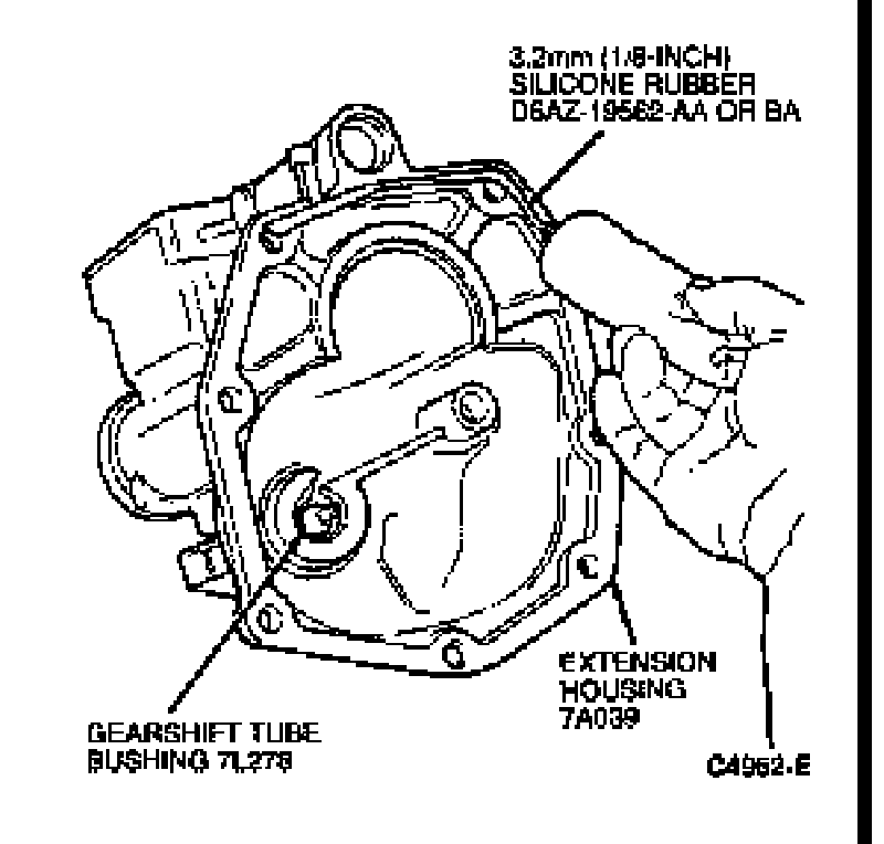
30. Coat detent spring with petroleum jelly and install in offset lever. Lubricate detent plate and install detent ball in neutral position on plate. Position offset lever in extension housing with spring over detent ball.

31. Slide lever and extension housing into position as an assembly.
NOTE:Make sure lubrication funnel engages into fifth-gear synchronizer.
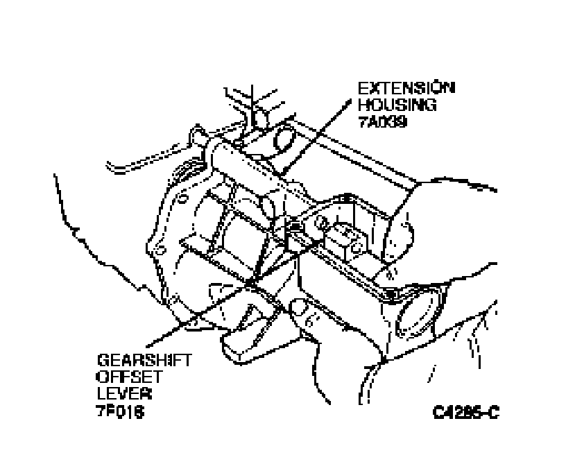
32. Press downward on offset lever to compress detent spring and push lever and housing into position.
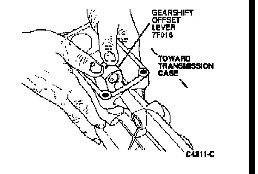
33. Install extension housing retaining bolts. Tighten to 47-61 Nm (30-45 lb-ft).
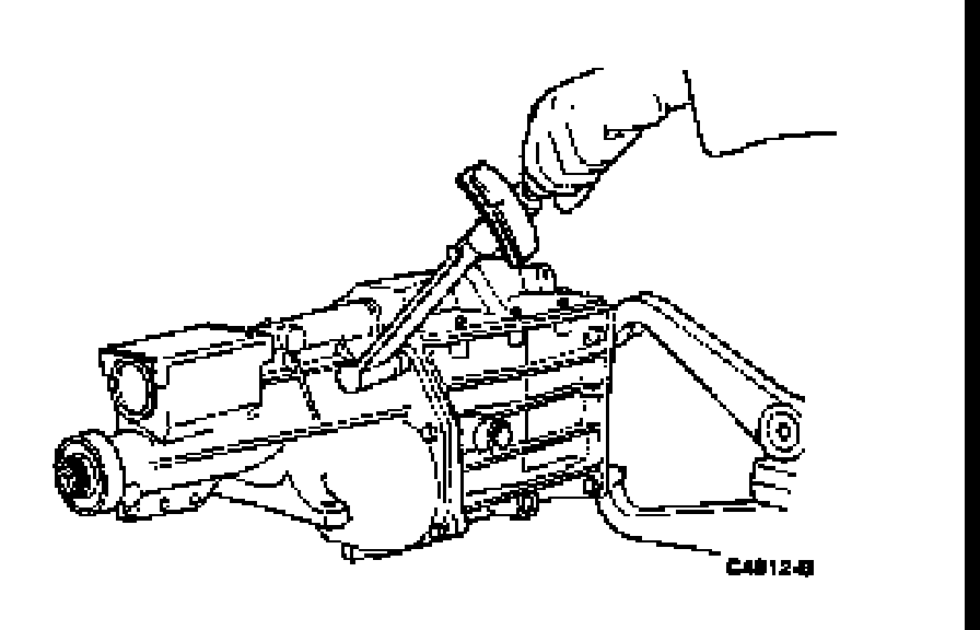
34. Using a suitable pin punch, align the hole in shifter shaft with hole in offset lever and install roll pin.
Install damper sleeve in offset lever .
NOTE:Output shaft geartrain end play must be checked and adjusted at this point.

35. Check output shaft geartrain end play as follows:
a. Rotate transmission to the vertical position with extension housing facing up.
b. Mount Dial Indicator D78P-4201-G or equivalent on the extension housing with the indicator stylus contacting the output shaft.
c. Rotate the input and output shafts. Zero the dial indicator.
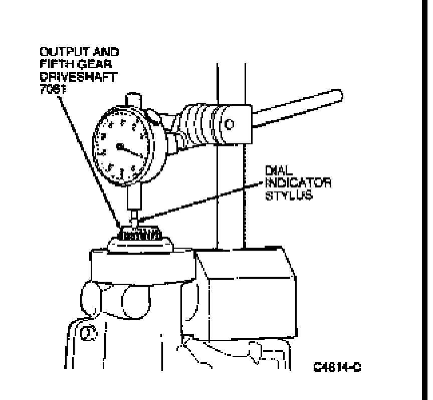
d. Using a wood block, push upward on the input shaft and note the dial indicator reading.
NOTE:A shim must be installed that is the thickness of the dial indicator reading. This will provide zero end play.
CAUTION: Thickest shim must be installed closest to the front bearing cup.
CAUTION: Although zero end play is the ideal end play specification, a plus or minus .050mm (0.002 inch) is an acceptable tolerance. Do not overload the bearings with too thick a shim.
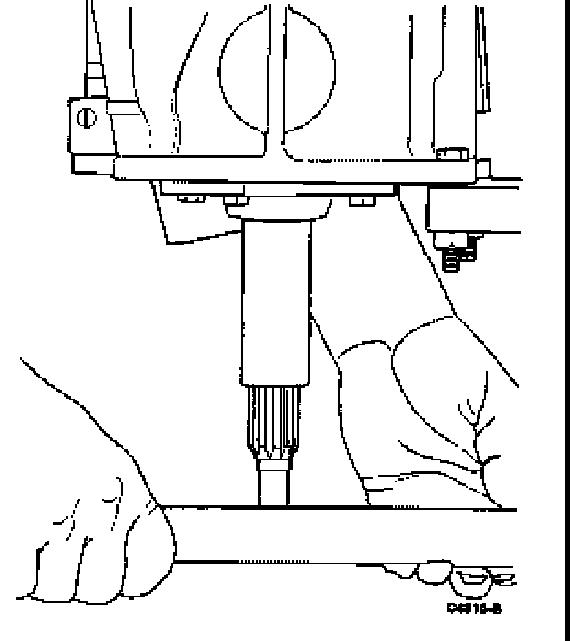
36. Rotate transmission to the horizontal position and remove the front bearing retainer. Remove bearing race from retainer and install the necessary shim(s).
37. Apply a 3.2mm (1/8 inch) bead of Silicone Rubber D6AZ-19562-AA or BA (ESB-M4G92-A) or equivalent to bearing retainer.
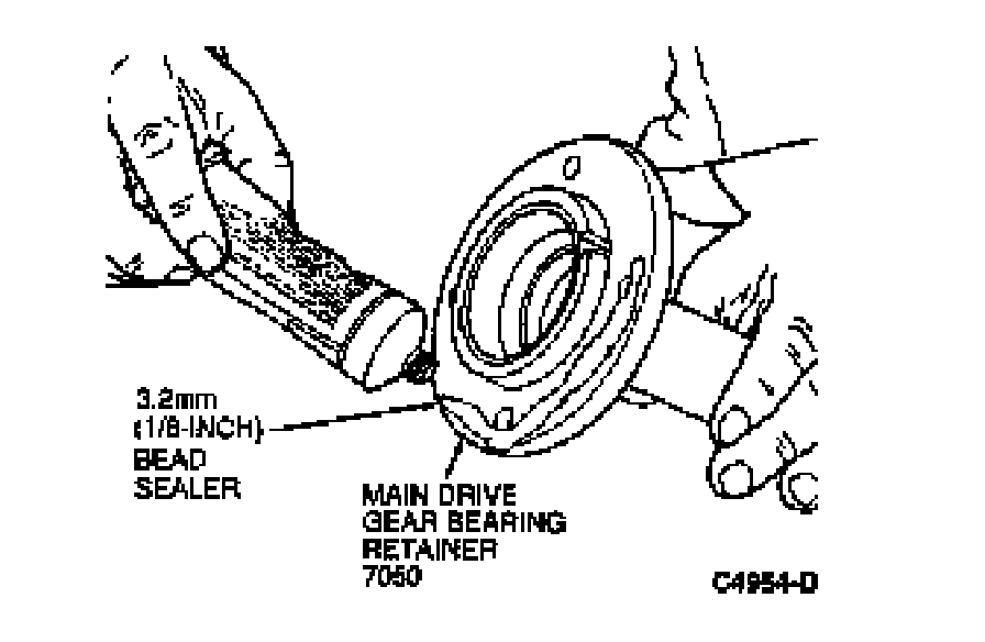
Install bearing retainer with narrow or smaller notch facing upward, and tighten retaining bolts to 15-27 Nm (11-20 lb-ft). Check end play.
CAUTION: The sealer must not cover the notch in the bearing retainer.
38. Apply a 3.2mm (1/8 inch) bead of Silicone Rubber D6AZ-19562-AA or BA (ESB-M4G92-A) or equivalent on the turret cover.
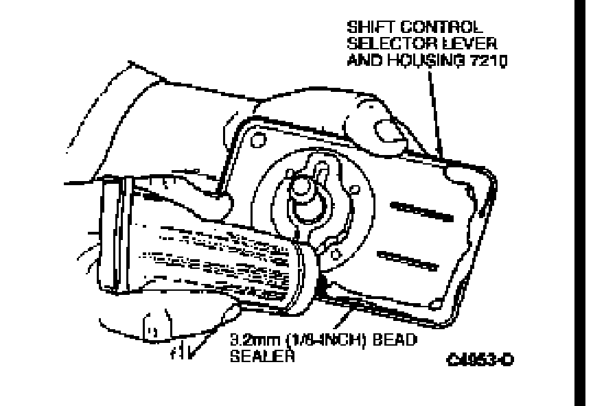
39. Position shift control selector lever and housing / turret cover on the extension housing and tighten the retaining bolts to 17-20 Nm (12-15 lb-ft).
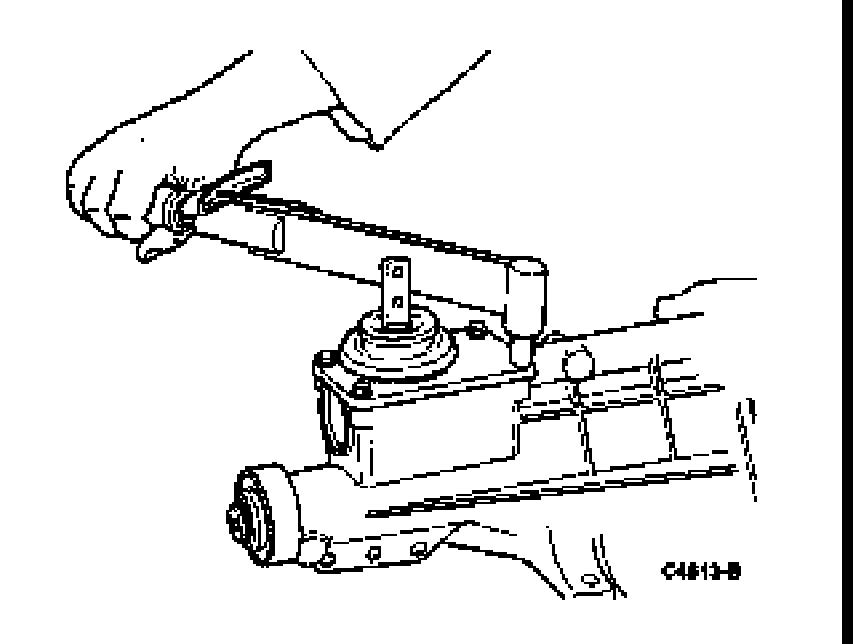
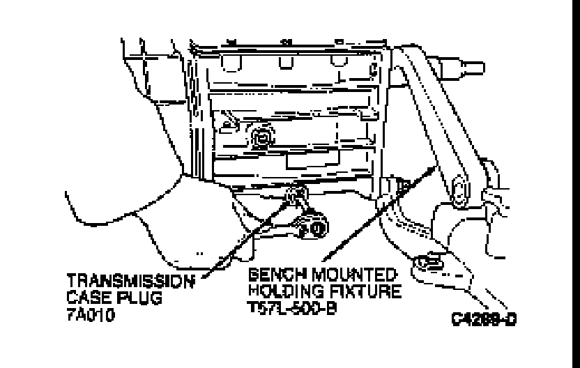
40. Install and tighten drain plug to 17-29 Nm (12-22 lb-ft).
Factory Service Tools
Use the Manual With the Right Hardware
Pair factory procedures with proven DIY tools so the instructions are easier to execute.
Disclosure: Verified tool recommendations may earn an affiliate commission at no cost to you.
When to See a Mechanic
Stop DIY work and contact a certified mechanic immediately if any of the following apply:
- • You smell fuel, burning insulation, or see smoke.
- • Brakes feel soft, pull hard to one side, or make grinding noises.
- • The engine overheats, stalls repeatedly, or misfires under load.
- • You are missing required tools, torque specs, or safe lifting equipment.
- • You are not confident in the next step or safety outcome.
Rather have a pro handle this?
A certified mobile mechanic comes to your home or office. They bring the tools, you stay comfortable. No tow truck, no waiting room, no surprises.
Comes to youSame-day available12-month warranty
Get a Free QuoteNo obligation. See pricing before you book.