
Safety Warning
DIY auto repair can cause serious injury, fire, or vehicle damage. These guides are for informational purposes only. Always follow OEM torque specs, wear PPE, and consult a certified mechanic if you are unsure. You are solely responsible for your safety.
2013 Chevrolet Malibu L4-2.4L HybridFACTORY OEM SERVICE PROCEDURE
Engine Replacement
Engine Replacement
Removal Procedure
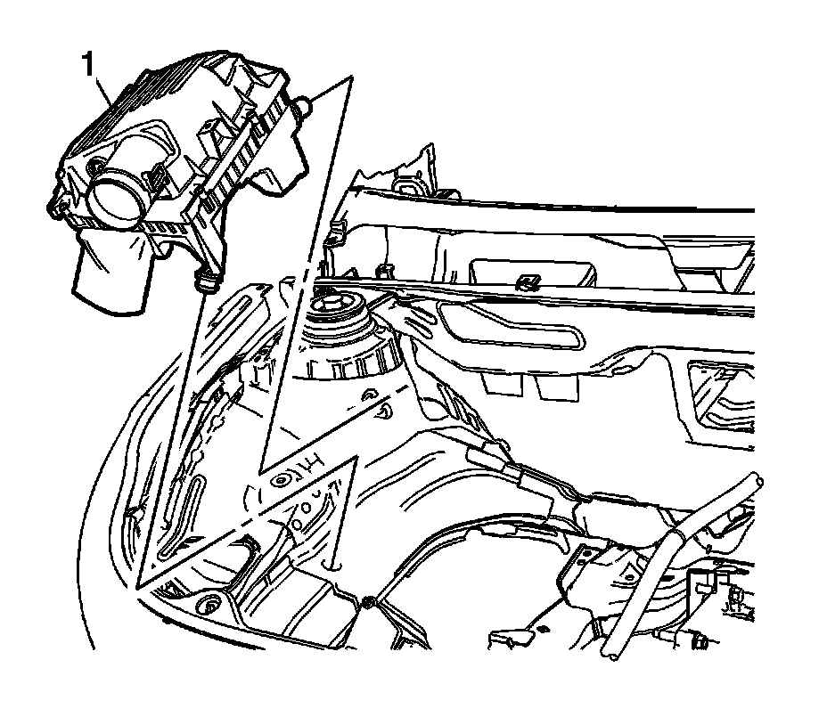
1. Remove the air cleaner assembly. Refer to Air Cleaner Assembly Replacement Service and Repair.
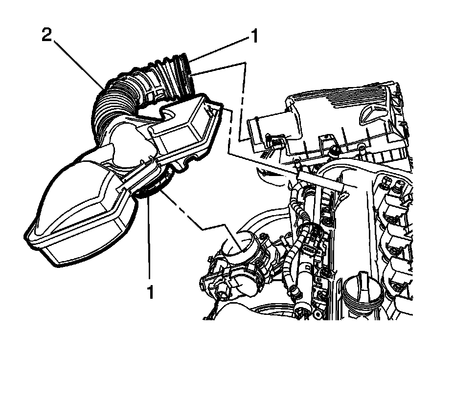
2. Remove the air cleaner outlet duct assembly. Refer to Air Cleaner Outlet Duct Replacement Service and Repair.
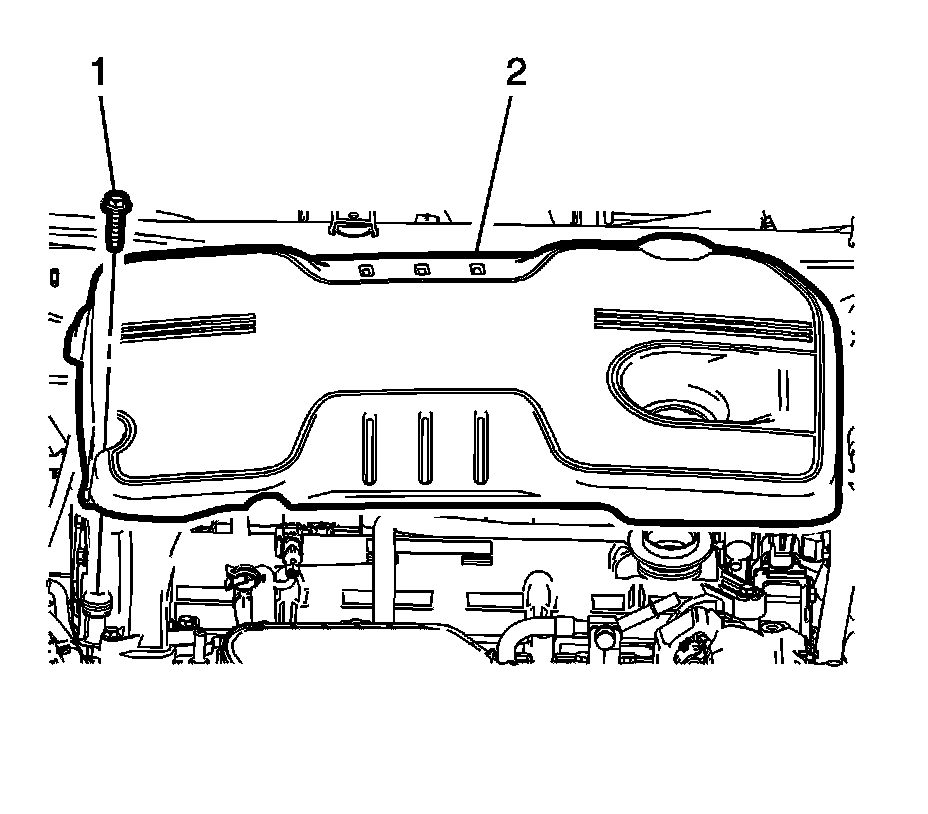
3. Remove the intake manifold cover (2). Refer to Intake Manifold Cover Replacement Intake Manifold Cover Replacement.
4. Relieve the fuel system pressure. Refer to Fuel Pressure Relief Service and Repair.
5. Disconnect the fuel feed pipe quick connect fitting at the fuel pump and unclip the pipe from the engine bracket. Refer to Metal Collar Quick Connect Fitting Service Metal Collar Quick Connect Fitting Service.
6. Disconnect the evaporative emission (EVAP) line quick connect fitting from the EVAP purge solenoid. Refer to Plastic Collar Quick Connect Fitting Service Plastic Collar Quick Connect Fitting Service.
7. Drain the cooling system. Refer to Cooling System Draining and Filling (GE 47716) Cooling System Draining and Filling (GE 47716)Cooling System Draining and Filling (Static Fill) Cooling System Draining and Filling (Static Fill).
8. Remove the battery tray. Refer to Battery Tray Replacement Service and Repair.
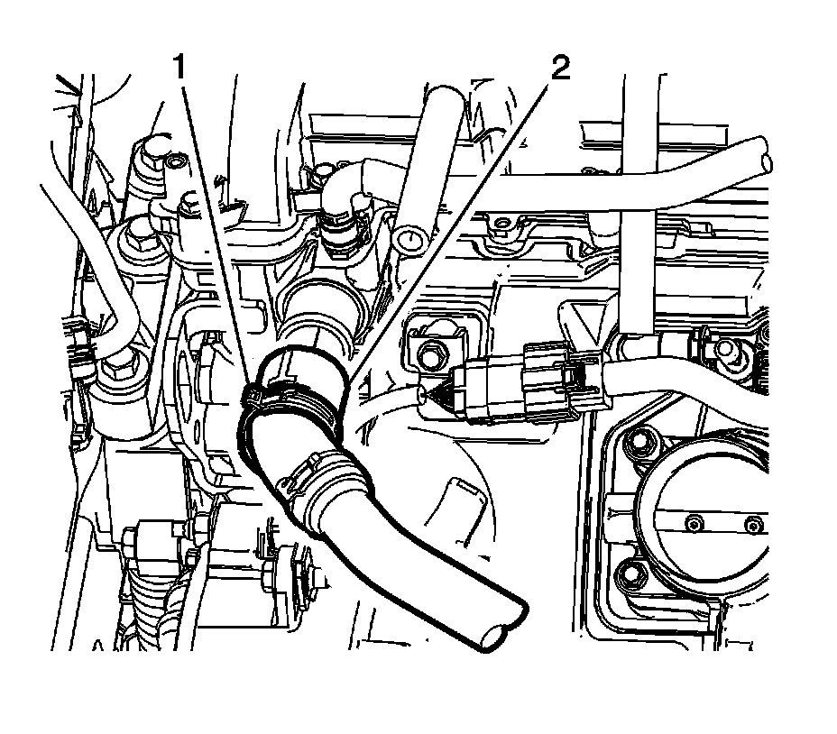
9. Reposition the hose clamp (1) and disconnect the radiator inlet hose (2). Refer to Radiator Inlet Hose Replacement (LUK) Radiator Inlet Hose ReplacementRadiator Inlet Hose Replacement (LCV) Radiator Inlet Hose ReplacementRadiator Inlet Hose Replacement (LTG) Radiator Inlet Hose Replacement.
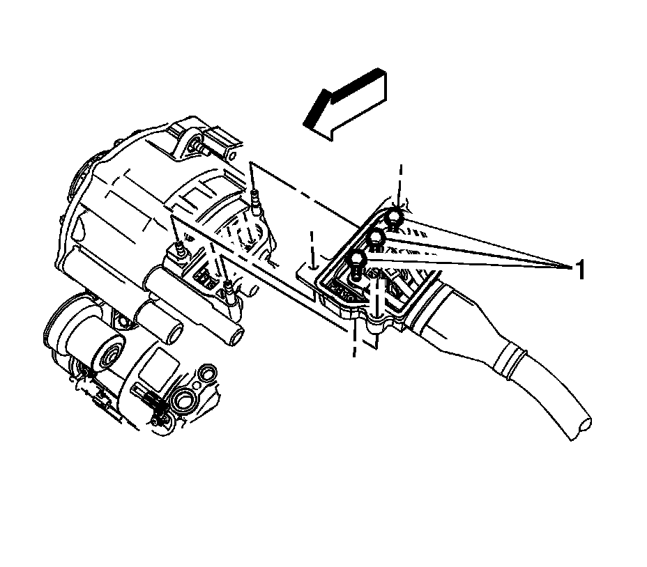
10. Remove the starter generator. Refer to Starter Generator Replacement Starter Generator Replacement.
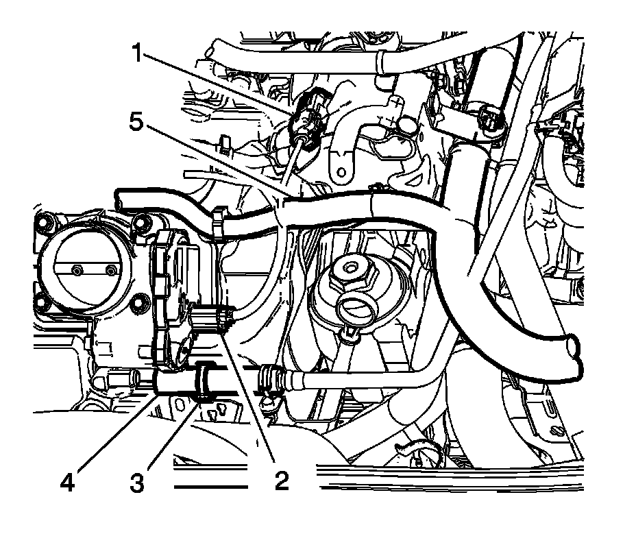
11. Reposition the vacuum brake booster hose clamp (3) at the intake manifold.
12. Disconnect the vacuum brake booster hose (4) from the intake manifold. Reposition the brake booster hose out of the way.
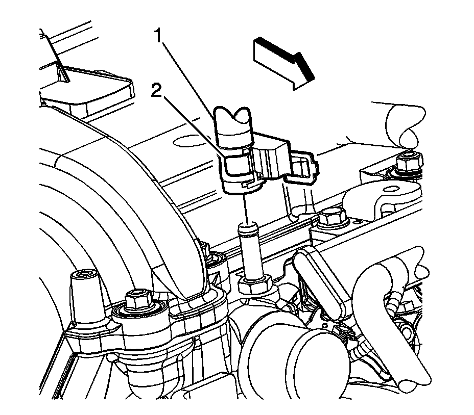
13. Reposition the coolant recovery inlet hose clamp (2) at the cylinder head.
14. Disconnect the coolant recovery inlet pipe clip from the fuel pump cover.
15. Disconnect the coolant recovery inlet hose (1) from the cylinder head. Reposition the hose/pipe out of the way.
16. Remove the radiator outlet hose. Refer to Radiator Outlet Hose Replacement (LUK) Radiator Outlet Hose ReplacementRadiator Outlet Hose Replacement (LCV) Radiator Outlet Hose ReplacementRadiator Outlet Hose Replacement (LTG) Radiator Outlet Hose Replacement.
17. Disconnect the heater inlet hose at the heater core.
18. Disconnect the heater outlet hose at the heater core.
19. Disconnect the surge tank hose at the thermostat housing.
20. Disconnect the auxiliary radiator inlet hose from the generator coolant pump. Refer to Auxiliary Radiator Inlet Hose Replacement Auxiliary Radiator Inlet Hose Replacement.
21. Disconnect the auxiliary radiator outlet hose at the auxiliary coolant pump. Refer to Auxiliary Heater Outlet Hose Replacement (LUK) Auxiliary Heater Outlet Hose Replacement.
22. Raise and support the vehicle. Refer to Lifting and Jacking the Vehicle Service and Repair.
23. Drain the engine oil. Refer to Engine Oil and Oil Filter Replacement Service and Repair.
24. Remove the secondary air injection pump, if equipped. Refer to Secondary Air Injection Pump Replacement Service and Repair.
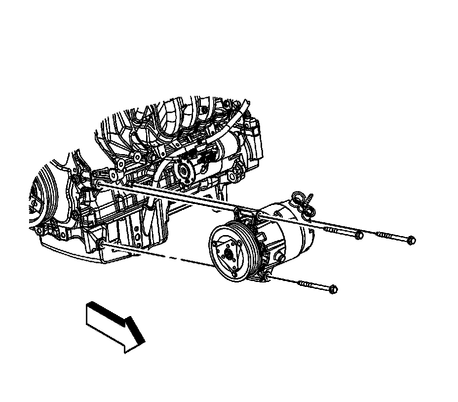
25. Unbolt the A/C compressor and reposition out of the way.
26. Remove the starter motor. Refer to Starter Replacement (LUK) Service and RepairStarter Replacement (LCV,LTG) Service and Repair
27. Remove the front wheels and tires. Refer to Tire and Wheel Removal and Installation Service and Repair.
28. Remove the front wheelhouse front liner. Refer to Front Wheelhouse Front Liner Replacement (Left Side) Service and RepairFront Wheelhouse Front Liner Replacement (Right Side) Service and Repair.
29. Remove the front compartment splash shield. Refer to Front Compartment Splash Shield Replacement Service and Repair
30. Remove the catalytic converter. Refer to Catalytic Converter Replacement (LUK) Service and RepairCatalytic Converter Replacement (LCV) Service and RepairCatalytic Converter Replacement (LTG) Service and Repair.
31. Disconnect the tie rods from the steering knuckles. Refer to Steering Linkage Outer Tie Rod Replacement Steering Linkage Outer Tie Rod Replacement.
32. Disconnect the stabilizer links from the stabilizer shaft. Refer to Stabilizer Shaft Link Replacement Front Suspension.
33. Disconnect the lower control arms from the steering knuckles. Refer to Lower Control Arm Replacement Front Suspension.
34. Drain the transmission fluid.
35. Remove the left wheel drive shaft. Refer to Front Wheel Drive Shaft Replacement - Left Side Front Wheel Drive Shaft Replacement - Left Side.
Note: A piece of hardwood should be used between the transaxle and the frame. This wood will support the engine when the left side engine mount bolts are removed.
36. Install a piece of hardwood 1 x 2 x 4 between the transaxle and the frame.
Note: A piece of hardwood should be used between the oil pan and the frame. This wood will support the engine when the right side engine mount bolts are removed.
37. Install a piece of hardwood 1 x 2 x 4 between the oil pan and the frame.
38. Remove the transaxle oil cooler hoses from the transaxle. Refer to Transmission Fluid Cooler Outlet Pipe Replacement (LUK) 6T40 (MH8,MHH) - Automatic TransmissionTransmission Fluid Cooler Outlet Pipe Replacement (LCV) 6T40 (MH8,MHH) - Automatic Transmission and Transmission Fluid Cooler Inlet Pipe Replacement (LUK) 6T40 (MH8,MHH) - Automatic TransmissionTransmission Fluid Cooler Inlet Pipe Replacement (LCV) 6T40 (MH8,MHH) - Automatic Transmission.
39. Lower the vehicle.
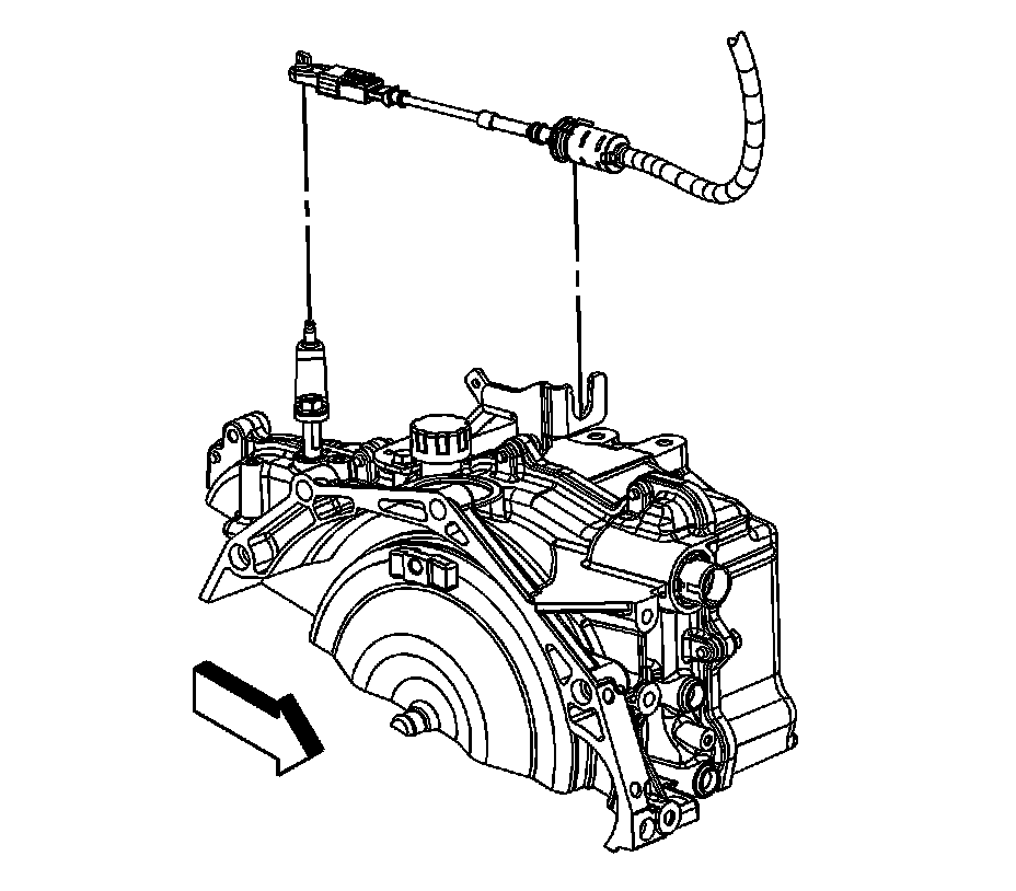
40. Remove the transaxle shift cable from the range select lever.
41. Release the shift control cable retaining clip and remove the cable from the shift control cable bracket.
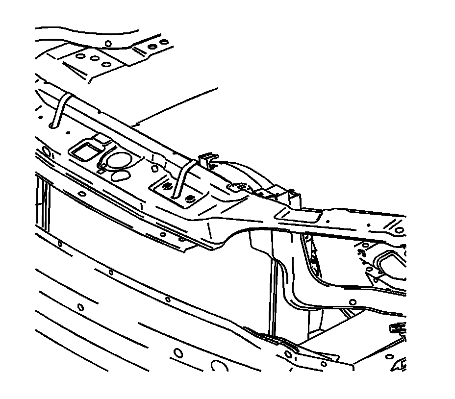
Note: The radiator/condenser/fan assembly will stay in the vehicle during engine removal.
42. Using long tie straps, secure the radiator/condenser/fan assembly to the radiator support.
43. Disconnect the intermediate shaft from the steering gear. Refer to Intermediate Steering Shaft Replacement Intermediate Steering Shaft Replacement.
44. Remove the engine mount to bracket bolts.
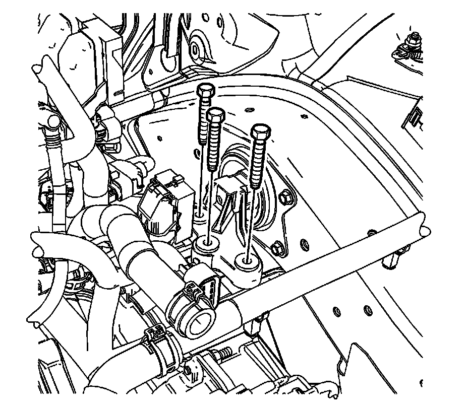
45. Remove the transaxle mount to transaxle bolts.
46. Disconnect the negative battery cable at the left frame rail.
47. Disconnect the following electrical connectors:
* ECM connectors
* Transmission connector
* Engine harness connector at the underhood fuse block
* Main engine harness to body harness connector
* Transmission auxiliary fluid pump connector
48. Position the disconnected engine harness on the engine
49. Raise the vehicle.
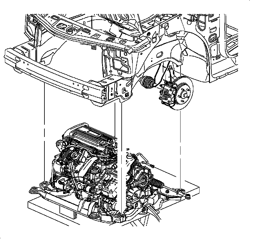
Note: During the powertrain removal support the vehicle body by placing a jack at the rear of the vehicle.
50. Position an engine support table under the powertrain assembly.
Note: Blocks of wood can be used between the front of the frame and the oil pan to table in order to level the powertrain during the removal.
51. With the table positioned, fully raise the table to contact with the powertrain assembly.
52. Remove the frame to body bolts. Refer to Drivetrain and Front Suspension Frame Replacement Service and Repair.
Note: When lowering the engine/transaxle assembly, verify all brake pipes, shifter cables and other components are not interfering with the removal.
53. Carefully lower the engine table and raise the body on the hoist until the engine/transaxle and frame are separated from the vehicle.
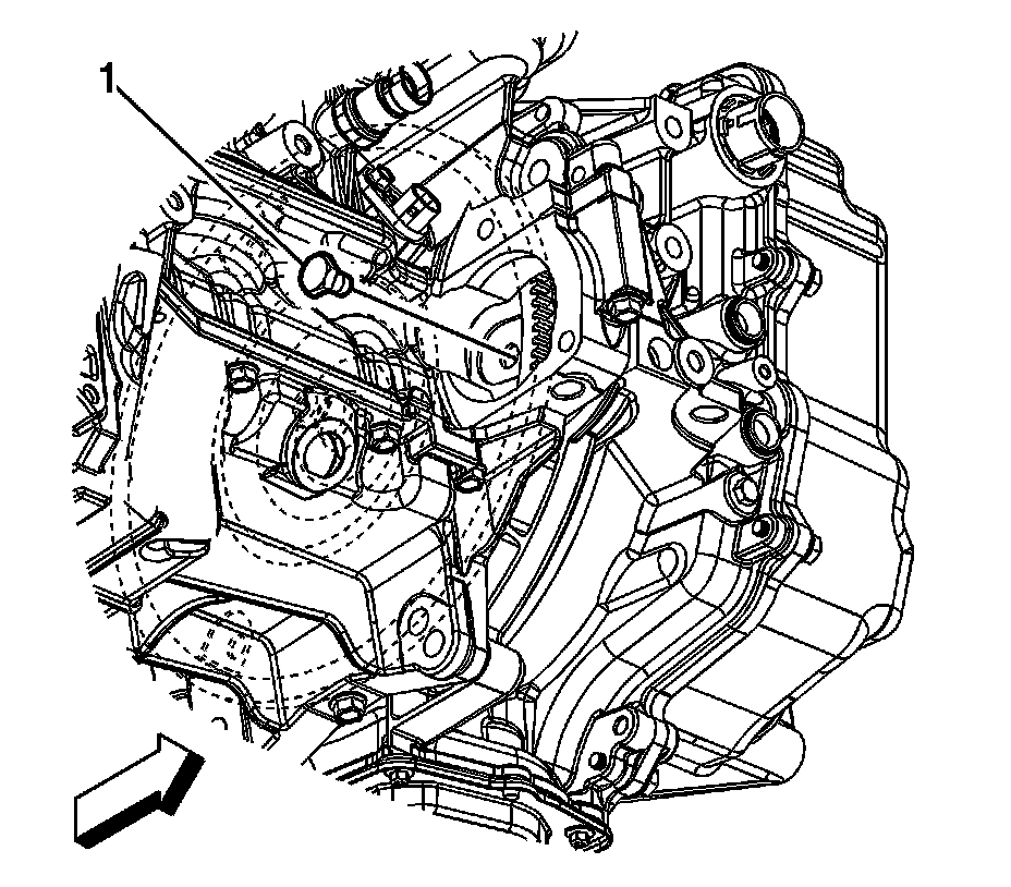
54. Remove the torque converter to flexplate bolts (1).
55. Remove the intermediate drive shaft. Refer to Front Wheel Drive Intermediate Shaft Replacement Front Wheel Drive Intermediate Shaft Replacement.
56. Install a suitable lifting device to the engine.
57. Disconnect the engine harness connectors as necessary.
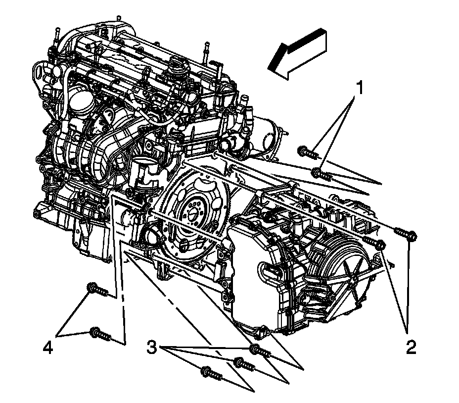
58. Remove the transaxle bolts from the engine (2).
59. Separate the engine from the transaxle.
60. Install the engine to a suitable engine stand.
61. Transfer parts as necessary.
Installation Procedure
1. Install a suitable lifting device to the engine.
2. Using the lifting device, position and install the engine to the transaxle.
Caution: Refer to Fastener Caution Fastener Caution.
3. Install the transaxle bolts to the engine and tighten to 75 Nm (55 lb ft).
4. Install the torque converter to flexplate bolts (1) and tighten to 60 Nm (44 lb ft).
5. Remove the engine lifting device.
6. Install the intermediate drive shaft. Refer to Front Wheel Drive Intermediate Shaft Replacement Front Wheel Drive Intermediate Shaft Replacement.
7. Position the powertrain support table under the vehicle.
8. Raise the powertrain into position under the vehicle.
9. With the table positioned, if required, lower the vehicle over the powertrain.
10. Align the lower radiator pins with the frame. Ensure all hoses and electrical harnesses are correctly routed and free from the loading path of the powertrain.
11. Install the NEW frame to body bolts. Refer to Drivetrain and Front Suspension Frame Replacement Service and Repair.
12. Lower the vehicle.
13. Install the transaxle mount to transaxle bolts and tighten to 55 Nm (41 lb ft).
Note: The engine mount to bracket bolts must be hand started. Do not pry the engine mount to align the holes.
14. Install the engine mount. Refer to Engine Mount Replacement Engine Mount Replacement.
15. Connect the following electrical connectors:
* ECM connectors
* Transmission connector
* Engine harness connector at the underhood fuse block
* Main engine harness to body harness connector
* Transmission auxiliary fluid pump connector
16. Raise and support the vehicle.
17. Install the left wheel drive shaft. Refer to Front Wheel Drive Shaft Replacement - Left Side Front Wheel Drive Shaft Replacement - Left Side.
18. Connect the control arm to the steering knuckles. Refer to Lower Control Arm Replacement Front Suspension.
19. Connect the stabilizer links to the stabilizer shaft. Refer to Stabilizer Shaft Link Replacement Front Suspension.
20. Connect the outer tie rods to the steering knuckles. Refer to Steering Linkage Outer Tie Rod Replacement Steering Linkage Outer Tie Rod Replacement.
21. Connect the intermediate shaft to the steering gear. Refer to Intermediate Steering Shaft Replacement Intermediate Steering Shaft Replacement.
22. Install the catalytic converter. Refer to Catalytic Converter Replacement (LUK) Service and RepairCatalytic Converter Replacement (LCV) Service and RepairCatalytic Converter Replacement (LTG) Service and Repair.
23. Connect the transaxle oil cooler hoses to the transaxle. Refer to Transmission Fluid Cooler Outlet Pipe Replacement (LUK) 6T40 (MH8,MHH) - Automatic TransmissionTransmission Fluid Cooler Outlet Pipe Replacement (LCV) 6T40 (MH8,MHH) - Automatic Transmission and Transmission Fluid Cooler Inlet Pipe Replacement (LUK) 6T40 (MH8,MHH) - Automatic TransmissionTransmission Fluid Cooler Inlet Pipe Replacement (LCV) 6T40 (MH8,MHH) - Automatic Transmission.
24. Remove the wood from between the oil pan and the frame.
25. Remove the wood from between the transaxle and the frame.
26. Install the front wheelhouse front liner. Refer to Front Wheelhouse Front Liner Replacement (Left Side) Service and RepairFront Wheelhouse Front Liner Replacement (Right Side) Service and Repair.
27. Install the front compartment splash shield. Refer to Front Compartment Splash Shield Replacement Service and Repair.
28. Install the front wheels and tires. Refer to Tire and Wheel Removal and Installation Service and Repair.
29. Lower the vehicle.
30. Position the radiator/condenser/fan assembly. Remove the tie straps.
31. Install the shift control cable to the shift control cable bracket and engage the shift control cable retaining clip.
32. Install the transaxle shift cable to the range select lever.
33. Raise and support the vehicle.
34. Install the A/C compressor with the bolts and tighten to 50 Nm (37 lb ft).
35. Install the starter motor. Refer to Starter Replacement (LUK) Service and RepairStarter Replacement (LCV,LTG) Service and Repair.
36. Install the secondary air injection pump, if equipped. Refer to Secondary Air Injection Pump Replacement Service and Repair.
37. Lower the vehicle.
38. Connect the vacuum brake booster hose (4) at the intake manifold.
39. Install the vacuum brake booster hose clamp (3).
40. Install the starter generator. Refer to Starter Generator Replacement Starter Generator Replacement.
41. Connect the negative battery cable at the left frame rail.
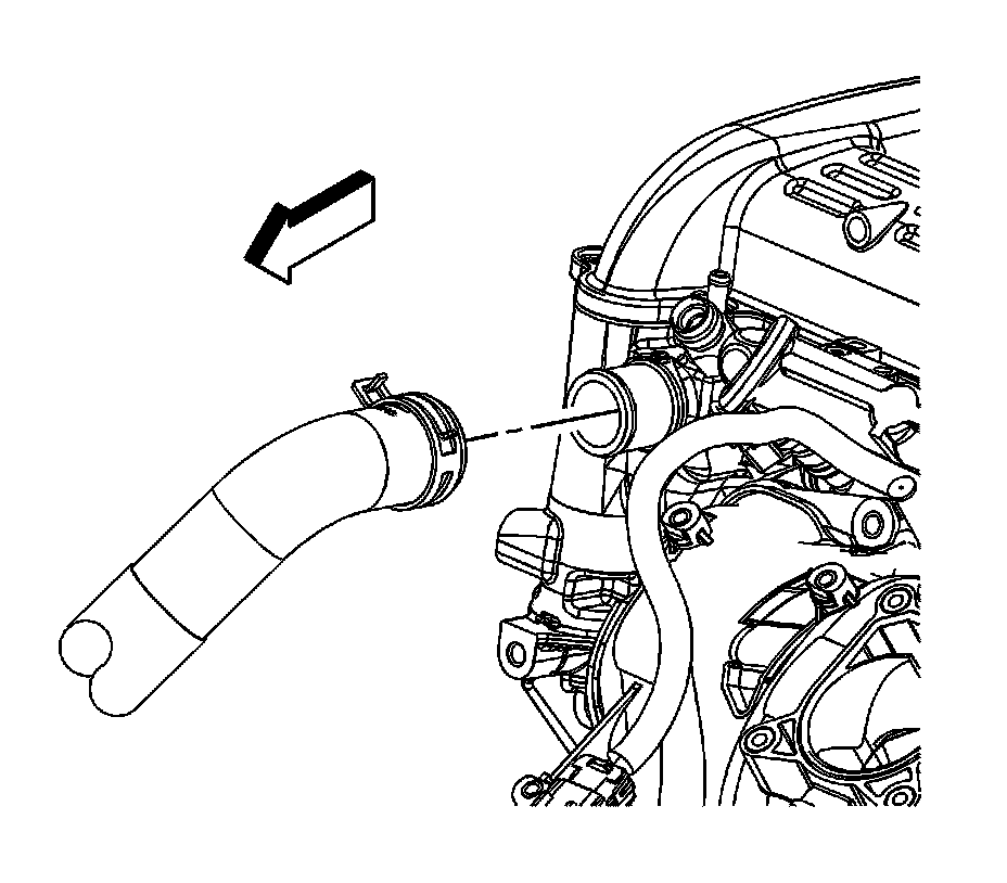
42. Install the radiator outlet hose. Refer to Radiator Outlet Hose Replacement (LUK) Radiator Outlet Hose ReplacementRadiator Outlet Hose Replacement (LCV) Radiator Outlet Hose ReplacementRadiator Outlet Hose Replacement (LTG) Radiator Outlet Hose Replacement.
43. Connect the heater inlet hose at the heater core.
44. Connect the heater outlet hose at the heater core.
45. Connect the surge tank hose at the thermostat housing.
46. Connect the auxiliary radiator inlet hose from the generator coolant pump. Refer to Auxiliary Radiator Inlet Hose Replacement Auxiliary Radiator Inlet Hose Replacement.
47. Connect the coolant recovery inlet hose (1) to the cylinder head.
48. Connect the coolant recovery inlet pipe clip to the fuel rail.
49. Position the coolant recovery inlet hose clamp (2) at the cylinder head.
50. Connect the radiator inlet hose (2) and reposition the hose clamp (1). Refer to Radiator Inlet Hose Replacement (LUK) Radiator Inlet Hose ReplacementRadiator Inlet Hose Replacement (LCV) Radiator Inlet Hose ReplacementRadiator Inlet Hose Replacement (LTG) Radiator Inlet Hose Replacement.
51. Install the battery tray. Refer to Battery Tray Replacement Service and Repair.
52. Connect the fuel feed pipe quick connect fitting at the fuel pump. Refer to Metal Collar Quick Connect Fitting Service Metal Collar Quick Connect Fitting Service.
53. Install the intake manifold cover (2). Refer to Intake Manifold Cover Replacement Intake Manifold Cover Replacement.
54. Install the air cleaner outlet duct assembly. Refer to Air Cleaner Outlet Duct Replacement Service and Repair.
55. Install the air cleaner assembly. Refer to Air Cleaner Assembly Replacement Service and Repair.
56. Fill the transaxle with fluid. Refer to Transmission Fluid Drain and Fill 6T40 (MH8,MHH) - Automatic Transmission.
57. Refill the engine with oil. Refer to Engine Oil and Oil Filter Replacement Service and Repair.
58. Perform the CKP system variation learn procedure. Refer to Crankshaft Position System Variation Learn Testing and Inspection.
59. Start the engine and allow the engine to run, inspect for leaks. Correct as necessary.
Factory Service Tools
Use the Manual With the Right Hardware
Pair factory procedures with proven DIY tools so the instructions are easier to execute.
Disclosure: Verified tool recommendations may earn an affiliate commission at no cost to you.
When to See a Mechanic
Stop DIY work and contact a certified mechanic immediately if any of the following apply:
- • You smell fuel, burning insulation, or see smoke.
- • Brakes feel soft, pull hard to one side, or make grinding noises.
- • The engine overheats, stalls repeatedly, or misfires under load.
- • You are missing required tools, torque specs, or safe lifting equipment.
- • You are not confident in the next step or safety outcome.
Rather have a pro handle this?
A certified mobile mechanic comes to your home or office. They bring the tools, you stay comfortable. No tow truck, no waiting room, no surprises.
Comes to youSame-day available12-month warranty
Get a Free QuoteNo obligation. See pricing before you book.