
Safety Warning
DIY auto repair can cause serious injury, fire, or vehicle damage. These guides are for informational purposes only. Always follow OEM torque specs, wear PPE, and consult a certified mechanic if you are unsure. You are solely responsible for your safety.
2012 Chevrolet Impala V6-3.6LFACTORY OEM SERVICE PROCEDURE
Front Subframe: Service and Repair
Frame Replacement
Special Tools
Removal Procedure
1.Install the engine support fixture to support the engine/transaxle assembly. Refer to Engine Support Fixture .
2.Raise and support the vehicle. Refer to Lifting and Jacking the Vehicle .
3.Remove the front tires and wheels. Refer to Tire and Wheel Removal and Installation .
4.Remove the lower radiator air deflector. Refer to Radiator Air Lower Baffle and Deflector Replacement .
5.Remove the positive battery cable retainers. Position the positive battery cable aside. Refer to Battery Positive and Negative Cable Replacement .
6.Disconnect the power steering cooler pipe from the frame. Refer to Power Steering Fluid Cooling Pipe Replacement .
7.Secure the power steering cooler to the exhaust pipe.
8.Remove the stabilizer shaft links. Rotate the stabilizer shaft up to gain access to the mounting bolts for the power steering gear. Refer to Stabilizer Shaft Link Replacement .
9.Remove the mounting fasteners for the power steering gear. Refer to Steering Gear Replacement .

10.Secure the power steering gear to the exhaust front pipe using mechanics wire.
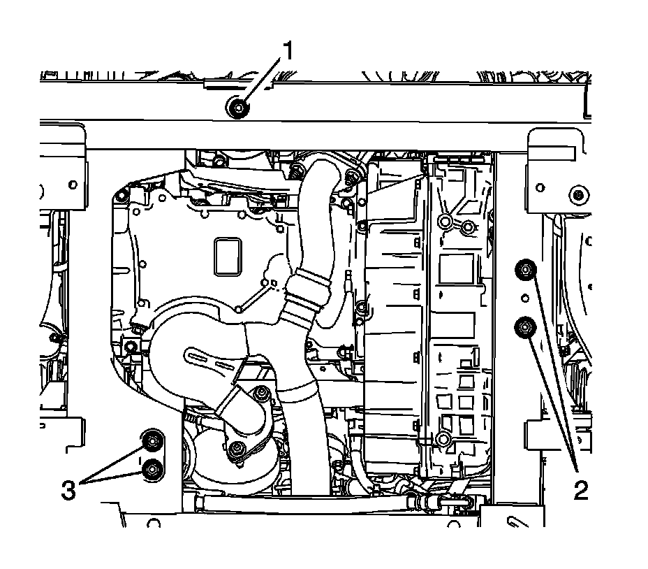
11.Remove the front engine mount to frame fastener (1).
12.Remove the rear engine mount to frame fasteners (3).
13.Loosen the transmission mount fasteners (2).
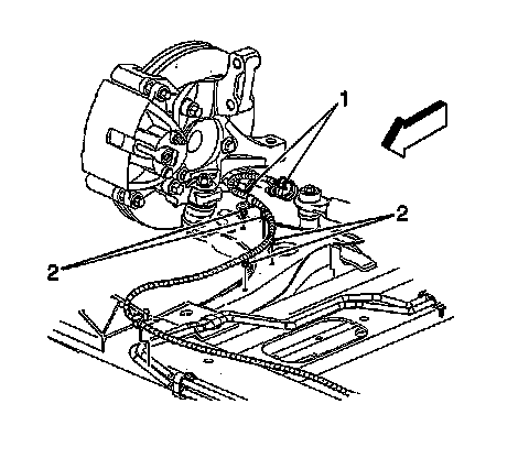
14.Disconnect both front wheel speed sensor connectors (1), if equipped.
15.Remove both front wheel speed harness retainers (2) from the frame and the lower control arms, if equipped.
16.Separate both of the lower ball joints from the steering knuckle. Refer to Lower Control Arm Ball Joint Replacement .
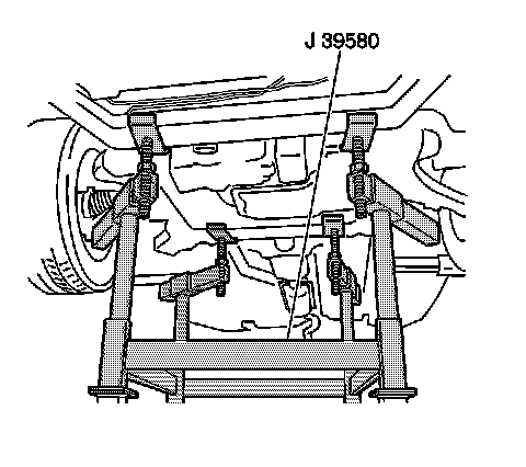
17.Lower the vehicle until the frame contacts
J 39580 table.
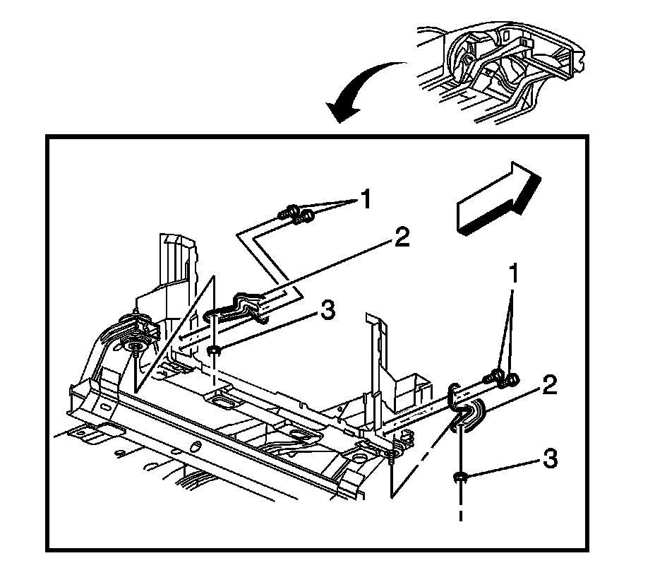
18.Remove the frame reinforcement nuts (3).
19.Remove the frame reinforcement bolts (1).
20.Remove the frame reinforcements (2).
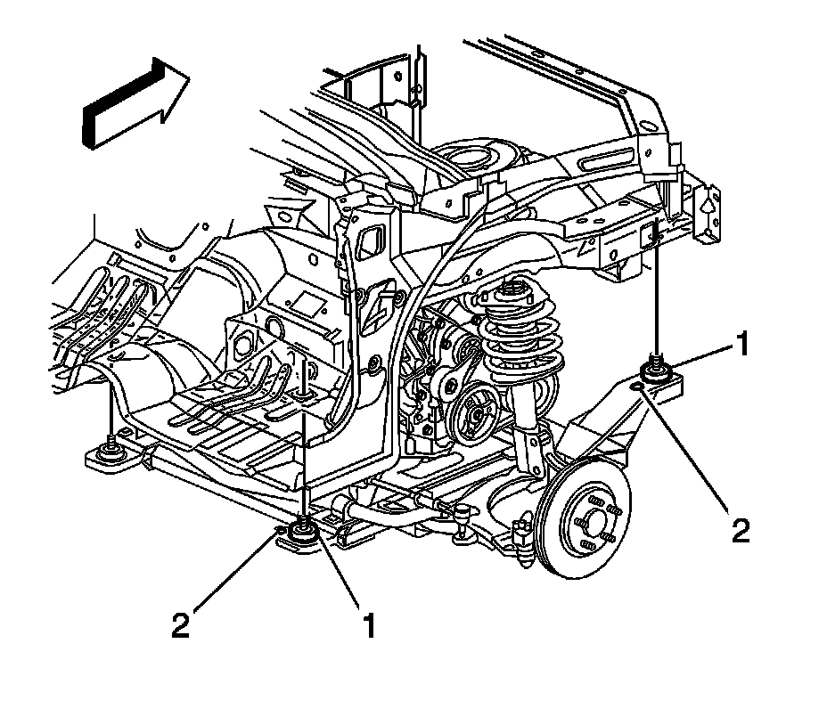
21.Remove the bolts (1) which secure the frame to the body.
22.Raise the vehicle in order to separate the frame from the body.
23.If replacement of the frame is necessary, remove the following components:
-Both of the lower control arms-Refer to Lower Control Arm Replacement .
-The stabilizer shaft-Refer to Stabilizer Shaft Replacement .
-The spacers, the upper insulator, the lower insulator, and the retainers-Refer to Drivetrain and Front Suspension Frame Front Insulator Replacement Service and Repair and to Drivetrain and Front Suspension Frame Rear Insulator Replacement .
Installation Procedure
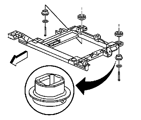
1.If a new frame is being installed, install the following components:
-Both of the lower control arms-Refer to Lower Control Arm Replacement .
-The stabilizer shaft-Refer to Stabilizer Shaft Replacement .
-The spacers, the upper insulator, the lower insulator, and the retainers-Refer to Drivetrain and Front Suspension Frame Front Insulator Replacement Service and Repair and to Drivetrain and Front Suspension Frame Rear Insulator Replacement .
2.Position the engine support table with the frame under the vehicle.
3.Lower the vehicle to the frame.
4.Loosely install the bolts (1) to secure the frame to the body.
Caution:Refer to Fastener Caution .
5.Align the frame to the body by inserting two 19X203 mm (0.74X8.0 in) pins in the alignment holes (2) on the right side of the frame.
Tighten
-Tighten the new front frame bolts to 145 N �m (107 lb ft).
-Tighten the new rear frame bolts to 160 N �m (118 lb ft).
6.Install the frame reinforcements (2).
7.Install the frame reinforcement bolts (1).
TightenTighten the bolts to 20 N �m (15 lb ft).
8.Install the frame reinforcement nuts (3).
TightenTighten the nuts to 20 N �m (15 lb ft).
9.Connect both the lower ball joints to the steering knuckle. Refer to Lower Control Arm Ball Joint Replacement .
10.Install the front engine mount to frame fastener (1) and tighten to 80 N �m (59 lb ft).
11.Remove the rear engine mount to frame fasteners (3) to 52 N �m (38 lb ft).
12.Loosen the transmission mount fasteners (2) to 52 N �m (38 lb ft).
13.Remove the power steering gear from the exhaust pipe. Position to the frame.
14.Install the steering gear mounting fasteners. Refer to Steering Gear Replacement .
15.Install the stabilizer shaft links. Refer to Stabilizer Shaft Link Replacement .
16.Connect both front wheel speed sensor connectors (1), if equipped.
17.Install both front wheel speed harness retainers (2) to the frame and to the lower control arm, if equipped.
18.Install the positive battery cable. Refer to Battery Positive and Negative Cable Replacement .
19.Install the power steering cooler pipe. Refer to Power Steering Fluid Cooling Pipe Replacement .
20.Install the radiator lower air deflector. Refer to Radiator Air Lower Baffle and Deflector Replacement .
21.Install the front tires and wheels. Refer to Tire and Wheel Removal and Installation .
22.Lower the vehicle.
23.Remove the engine support fixture.
24.Inspect the front wheel alignment. Refer to Wheel Alignment Measurement .
Factory Service Tools
Use the Manual With the Right Hardware
Pair factory procedures with proven DIY tools so the instructions are easier to execute.
Disclosure: Verified tool recommendations may earn an affiliate commission at no cost to you.
When to See a Mechanic
Stop DIY work and contact a certified mechanic immediately if any of the following apply:
- • You smell fuel, burning insulation, or see smoke.
- • Brakes feel soft, pull hard to one side, or make grinding noises.
- • The engine overheats, stalls repeatedly, or misfires under load.
- • You are missing required tools, torque specs, or safe lifting equipment.
- • You are not confident in the next step or safety outcome.
Rather have a pro handle this?
A certified mobile mechanic comes to your home or office. They bring the tools, you stay comfortable. No tow truck, no waiting room, no surprises.
Comes to youSame-day available12-month warranty
Get a Free QuoteNo obligation. See pricing before you book.