
Safety Warning
DIY auto repair can cause serious injury, fire, or vehicle damage. These guides are for informational purposes only. Always follow OEM torque specs, wear PPE, and consult a certified mechanic if you are unsure. You are solely responsible for your safety.
2012 Chevrolet Express 2500 V8-4.8LFACTORY OEM SERVICE PROCEDURE
Crankshaft Position Sensor: Service and Repair
Crankshaft Position Sensor Replacement
Removal Procedure
Warning
Unless directed otherwise, the ignition and start switch must be in the OFF or LOCK position, and all electrical loads must be OFF before servicing any electrical component. Disconnect the negative battery cable to prevent an electrical spark should a tool or equipment come in contact with an exposed electrical terminal. Failure to follow these precautions may result in personal injury and/or damage to the vehicle or its components.
For Vehicles equipped with OnStar(R) (UE1) with Back Up Battery:
The Back Up Battery is a redundant power supply to allow limited OnStar(R) functionality in the event of a main vehicle battery power disruption to the VCIM (OnStar(R)module). Do not disconnect the main vehicle battery or remove the OnStar(R) fuse with the ignition key in any position other than OFF. Retained accessory power (RAP) should be allowed to time out or be disabled (simply opening the driver door should disable RAP) before disconnecting power. Disconnecting power to the OnStar(R) module in any way while the ignition is On or with RAP activated may cause activation of the OnStar(R) Back-Up Battery (BUB) system and will discharge and permanently damage the back-up battery. Once the Back-Up Battery is activated it will stay on until it has completely discharged. The BUB is not rechargeable and once activated the BUB must be replaced.
Note:
Perform the Crankshaft Position System Variation Learn Testing and Inspection when the CKP sensor is removed or replaced.
1. Disconnect the negative battery cable.
2. Raise the vehicle. Refer to Lifting and Jacking the Vehicle Service and Repair.
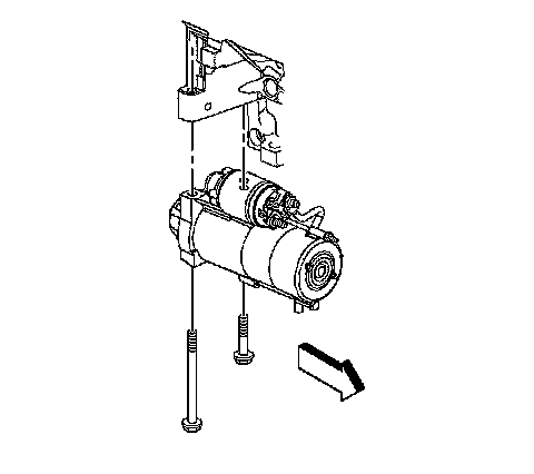
3. Remove the starter. Refer to Starter Replacement (Diesel) Service and RepairStarter Replacement (V8) Service and RepairStarter Replacement (V6) Service and Repair.
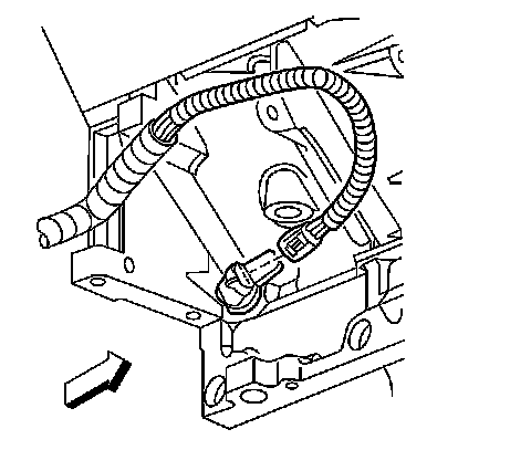
4. Disconnect the crankshaft position (CKP) sensor electrical connector.
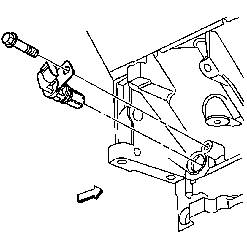
5. Clean the area around the CKP sensor before removal in order to avoid debris from entering the engine.
6. Remove the CKP sensor retaining fastener.
7. Remove the CKP sensor.
Installation Procedure
1. Install the CKP sensor.
Caution:
Refer to Fastener Caution Fastener Caution.
2. Install the CKP sensor retaining fastener and tighten to 25 Nm (18 lb ft).
3. Connect the CKP sensor electrical connector.
4. Install the starter. Refer to Starter Replacement (Diesel) Service and RepairStarter Replacement (V8) Service and RepairStarter Replacement (V6) Service and Repair.
5. Lower the vehicle.
6. Connect the negative battery cable.
7. Perform the CKP system variation learn procedure. Refer to Crankshaft Position System Variation Learn Testing and Inspection.
Factory Service Tools
Use the Manual With the Right Hardware
Pair factory procedures with proven DIY tools so the instructions are easier to execute.
Disclosure: Verified tool recommendations may earn an affiliate commission at no cost to you.
When to See a Mechanic
Stop DIY work and contact a certified mechanic immediately if any of the following apply:
- • You smell fuel, burning insulation, or see smoke.
- • Brakes feel soft, pull hard to one side, or make grinding noises.
- • The engine overheats, stalls repeatedly, or misfires under load.
- • You are missing required tools, torque specs, or safe lifting equipment.
- • You are not confident in the next step or safety outcome.