
Safety Warning
DIY auto repair can cause serious injury, fire, or vehicle damage. These guides are for informational purposes only. Always follow OEM torque specs, wear PPE, and consult a certified mechanic if you are unsure. You are solely responsible for your safety.
2009 Chevrolet Malibu L4-2.4L HybridFACTORY OEM SERVICE PROCEDURE
Generator Control Module Replacement
Generator Control Module Replacement
Special Tools
J 38185 Hose Clamp Pliers
Removal Procedure
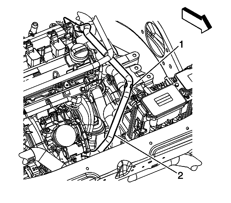
1. Disconnect the hybrid battery. Refer to Hybrid Battery Service Disconnect/Connect (Procedures).
2. Drain the cooling system. Refer to Cooling System Draining and Filling (Static Fill-LE5, LAT) (Service and Repair)Cooling System Draining and Filling (Static Fill-LY7, LZE, LZ4) (Service and Repair)Cooling System Draining and Filling (GE 47716) (Service and Repair).
3. Remove the battery tray. Refer to Battery Tray Replacement (LZ4, LY7, and LE5) (Service and Repair)Battery Tray Replacement (LAT) (Service and Repair).
4. Reposition the power brake booster vacuum hose (2) clamp at the intake manifold.
5. Remove the power brake booster vacuum hose from the intake manifold.
6. Remove the power brake booster vacuum hose from the clamp (2) on the generator control module coolant outlet hose.
7. Reposition the power brake booster vacuum hose out of the way.
Warning
To help avoid personal injury, additional precautions must be taken prior to working on the generator control module or the generator starter. After removing the 36V battery cables from the generator battery, remove both engine wiring harness connectors from the generator control module. Wait at least 5 minutes and then remove the generator control module cover. Verify voltage levels at all 36V, 12V, and 3-phase connections, are less than 3 volts using a DMM before proceeding.
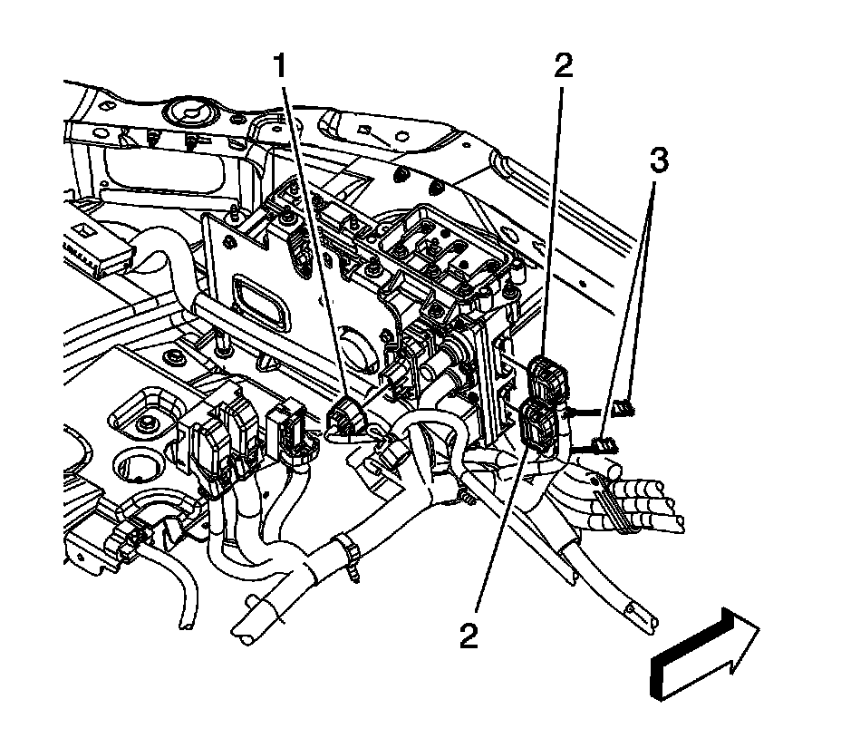
8. Remove the 2 connector position assurance (CPA) retainers (3).
9. Disconnect the 2 engine wiring harness electrical connectors (2) from the generator control module.
10. WAIT at least 5 minutes in order to allow the voltage stored in the generator control module to discharge.

11. Remove the generator control module bracket reinforcement bolt (1) and nuts (2).
12. Remove the generator control module bracket reinforcement (3).
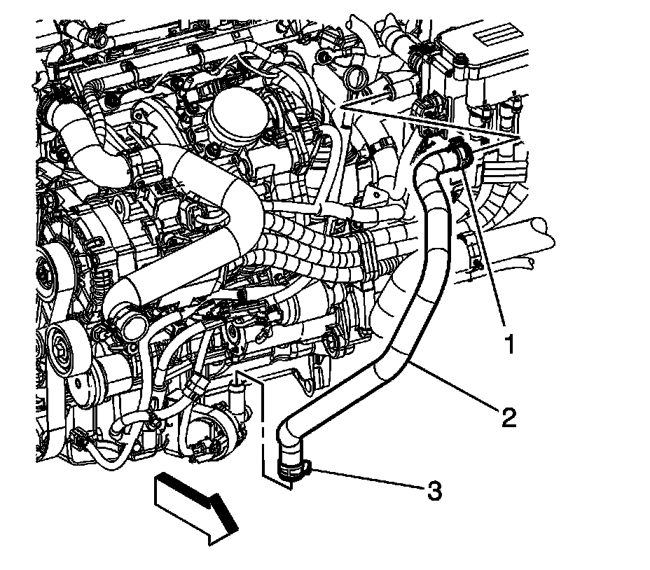
13. Reposition the generator control module coolant inlet hose clamp (1) at the generator control module using the J 38185 or equivalent.
14. Remove the generator control module coolant inlet hose (2) from the generator control module.
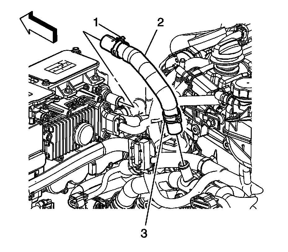
15. Reposition the generator control module coolant outlet hose clamp (1) at the generator control module using the J 38185 or equivalent.
16. Remove the generator control module coolant outlet hose (2) from the generator control module.
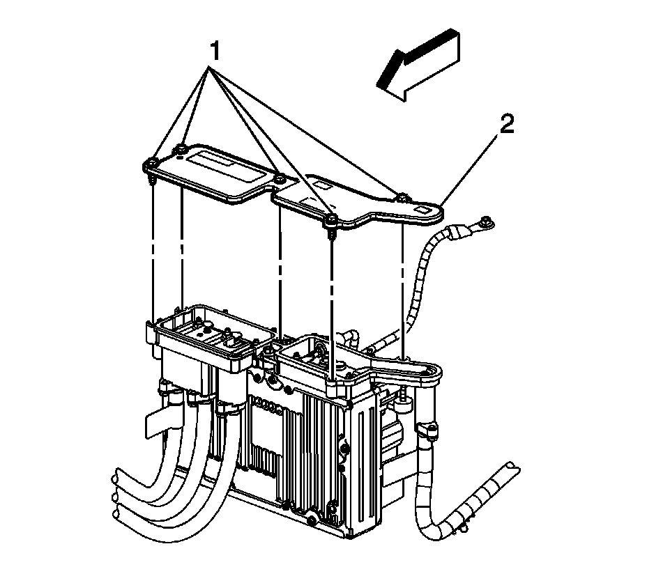
17. Loosen the generator control module cover integral bolts (1) and remove the cover (2).
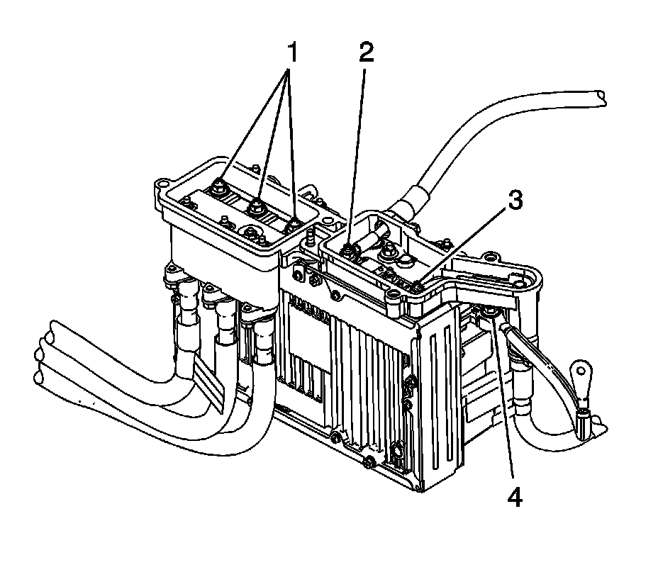
18. The generator control module will have to be checked for voltage potential using a voltmeter. First, verify that the voltmeter works:
1. Set the voltmeter to DC voltage.
2. Measure the vehicle 12-volt battery voltage.
3. The meter should read greater than +12 volts DC.
19. Check the generator control module for voltage potential, in order to ensure that the module has been disabled.
1. Measure from the 36-volt positive terminal (3) to a known good chassis ground. The voltage should be less than 3 volts.
2. Measure from the 12-volt positive terminal (2) to a known good chassis ground. The voltage should be less than 3 volts.
3. Measure from the ground terminal (4) to a known good chassis ground, checking for continuity.
Warning
To help avoid personal injury, always treat the 3-phase cable and connectors as if voltage is present and as if the surface of all parts of the cable is hot.
20. Verify that the generator control module 3-phase cables are disabled.
1. Measure from each phase 1, 2, and 3 connection (1) to a known good chassis ground. The voltage should be less than 3 volts.
2. After verifying that there is no voltage present, the generator control module 3-phase cables can now be removed from the generator control module.
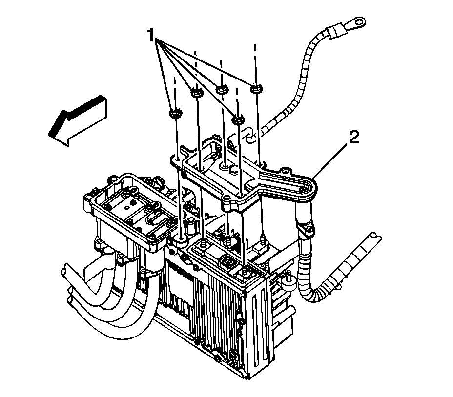
21. Remove the 36-volt terminal block nuts (1) from the generator control module.
22. Lift up, and reposition the 36-volt terminal block (2), secure the block out of the way. Discard the terminal block seal.
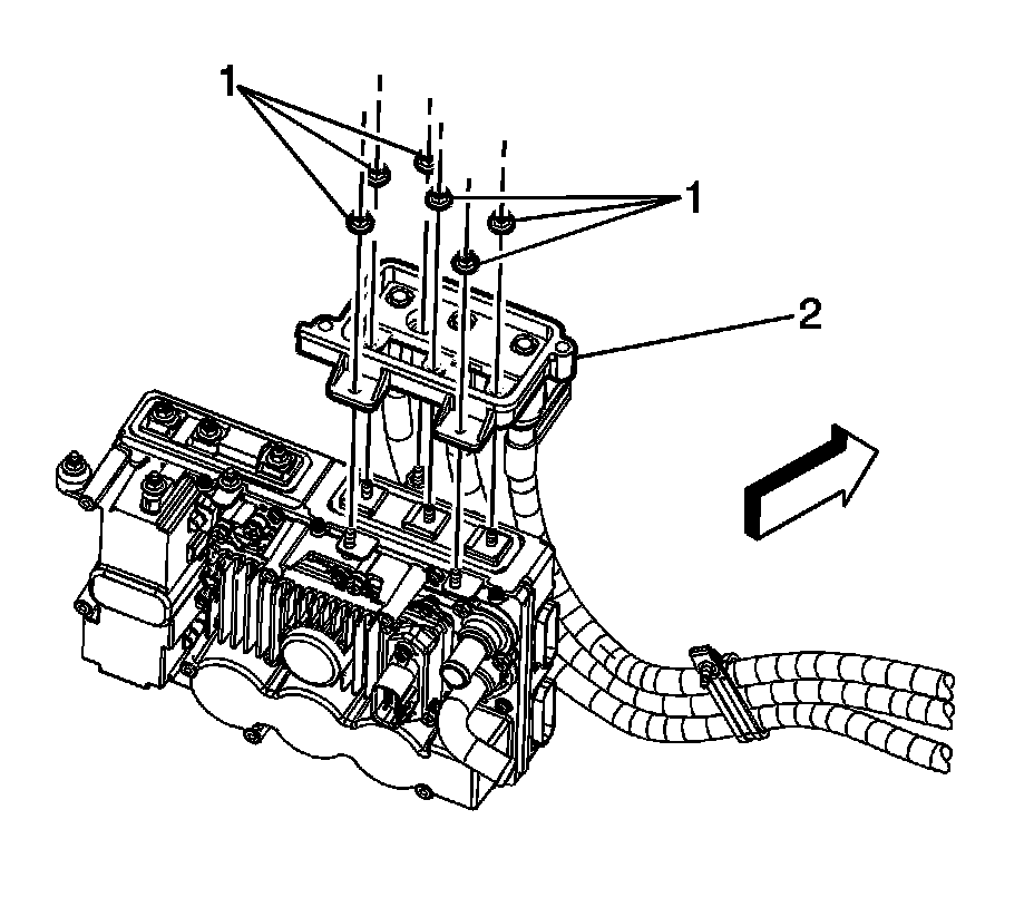
23. Remove the generator control module 3-phase cable terminal block nuts (1) from the generator control module.
24. Lift up, and reposition the generator control module 3-phase cable terminal block (2), secure the block out of the way. Discard the terminal block seal.
25. Disconnect the engine wiring harness electrical connector (1) from the transaxle auxiliary pump module.
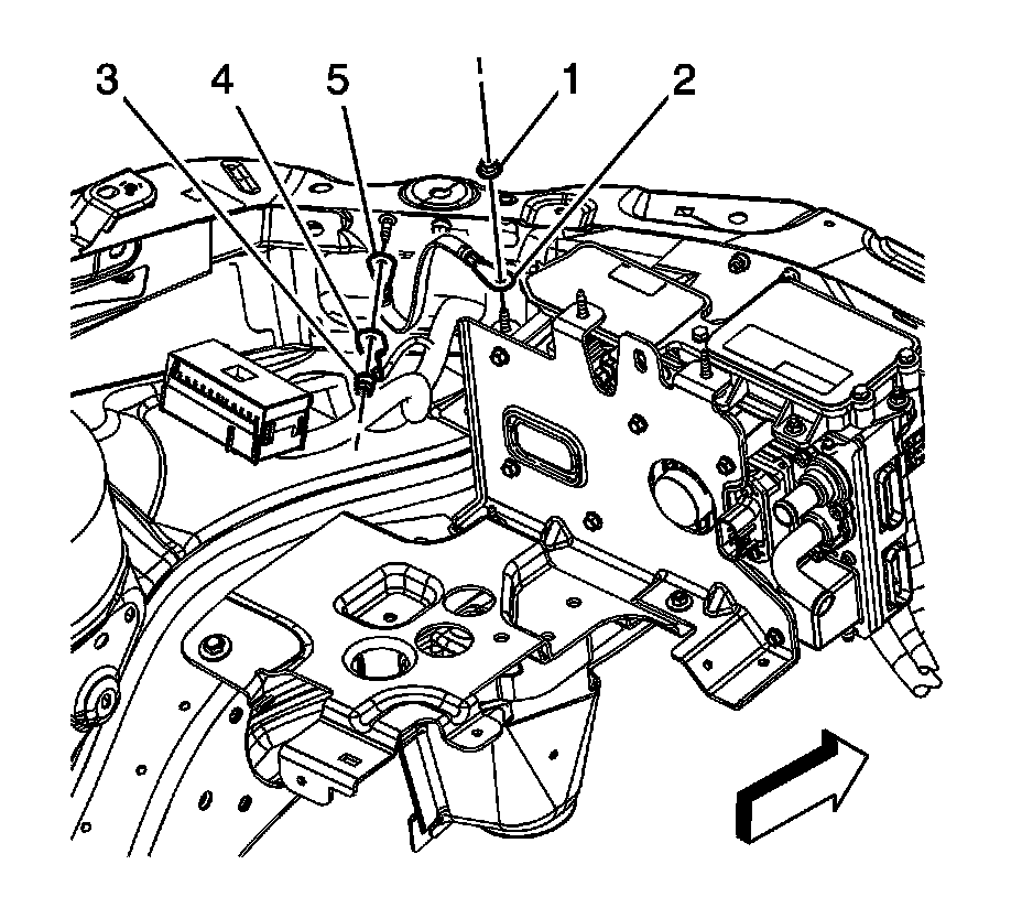
26. Remove the generator control module ground strap nut (1) and strap (2) from the module stud.
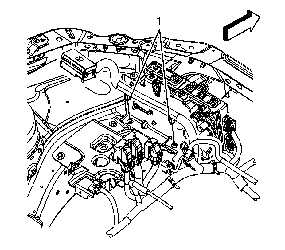
27. Remove the engine wiring harness clips (1) from the battery tray bracket studs.
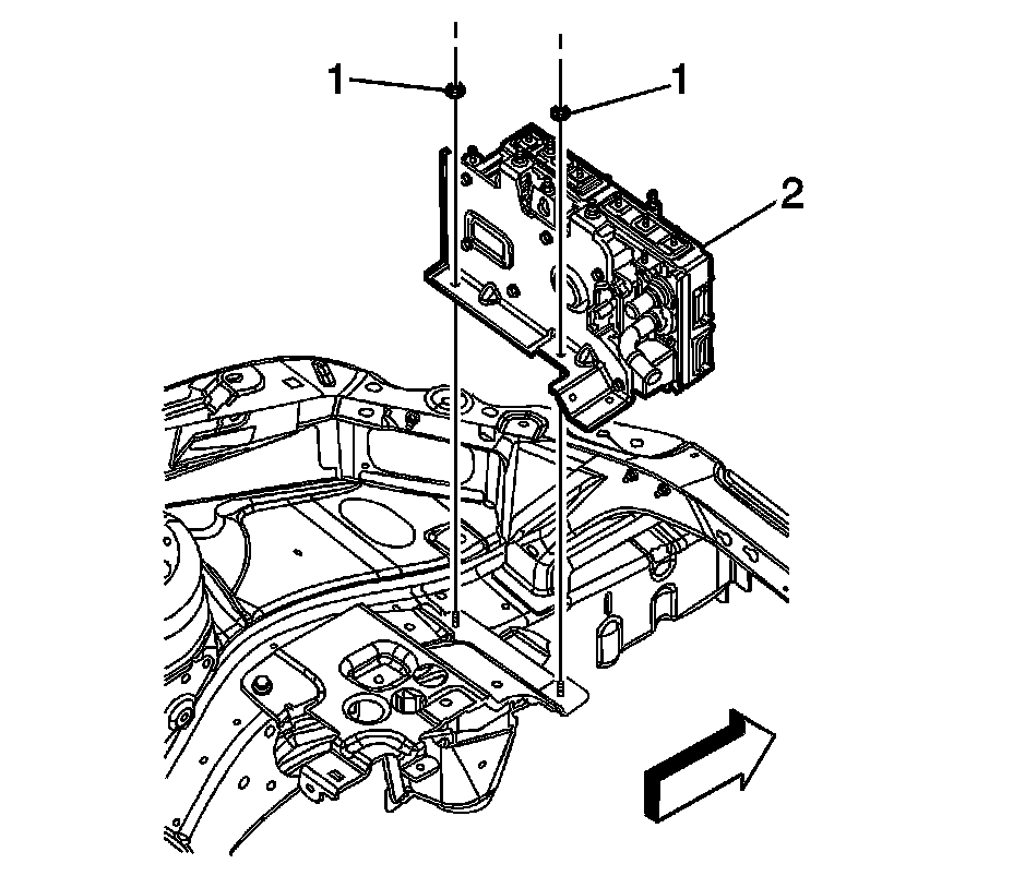
28. Remove the generator control module nuts (1).
29. Remove the generator control module (with bracket) (2) from the vehicle.
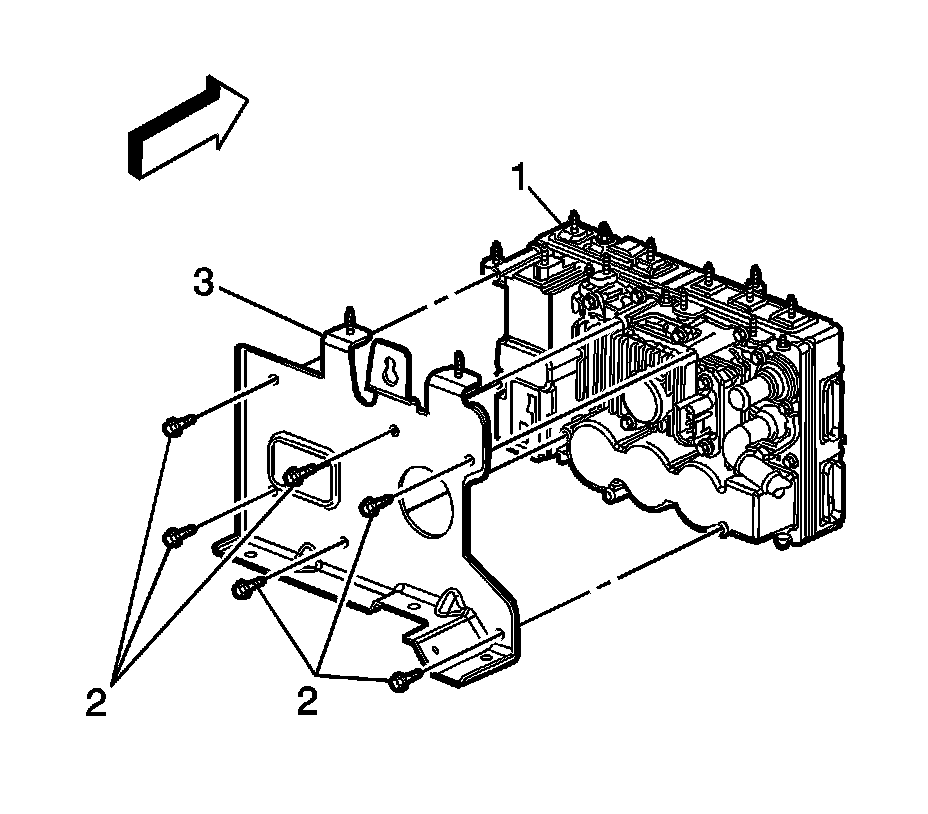
30. Place the generator control module assembly on a clean work surface.
31. Remove the generator control module bracket to module bolts (2). Separate the generator control module (1) from the bracket (3).
32. If replacing the generator control module. remove the transaxle auxiliary pump control module. Refer to Auxiliary Fluid Pump Control Module Replacement (Auxiliary Fluid Pump Control Module Replacement).
Installation Procedure
1. If the generator control module was replaced. install the transaxle auxiliary pump control module. Refer to Auxiliary Fluid Pump Control Module Replacement (Auxiliary Fluid Pump Control Module Replacement).
Caution: Refer to Fastener Caution (Fastener Caution).
2. Position the generator control module (1) to the bracket (3), and install the generator control module bracket to module bolts (2).
Tighten the bolts to 10 Nm (89 lb in).
3. Install the generator control module (with bracket) (2) to the vehicle.
4. Install the generator control module bracket nuts.
Tighten the nuts to 10 Nm (89 lb in).
5. Install the generator control module ground strap (2) to the stud and install the ground strap nut (1) to the module.
Tighten the nut to 10 Nm (89 lb in).
6. Connect the engine wiring harness electrical connector (1) to the transaxle auxiliary pump.
7. Place a NEW terminal block seal onto the generator control module.
8. Install the generator control module 3-phase cable terminal block (2) onto the generator control module.
9. Install the generator control module 3-phase cable terminal block nuts (1) until snug.
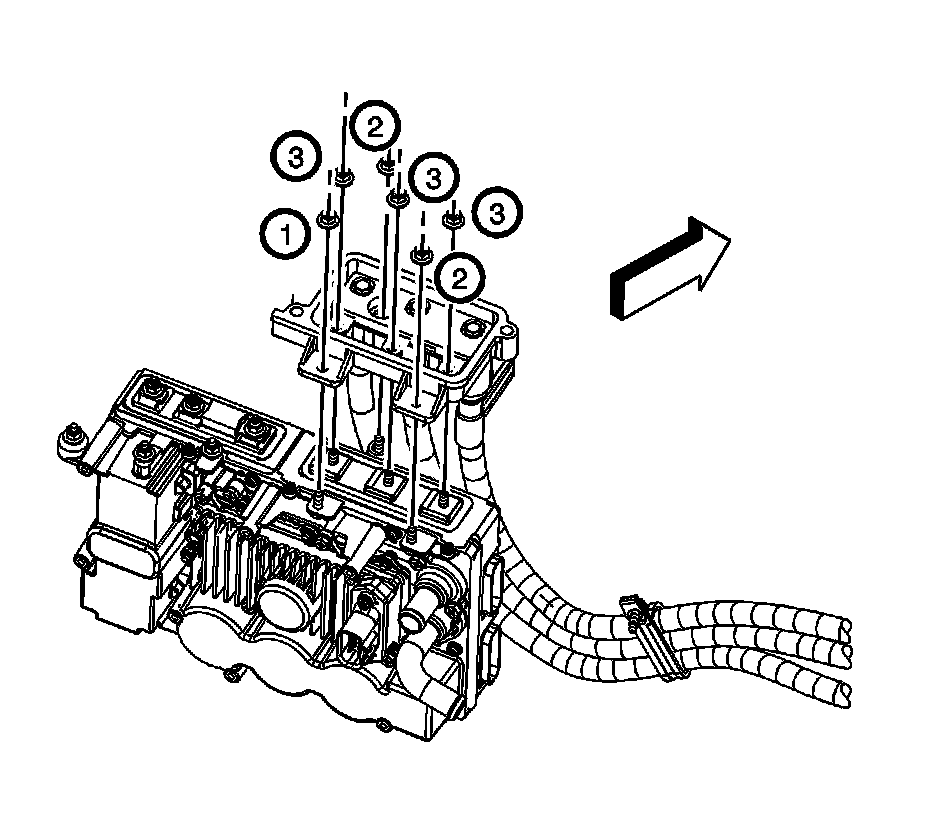
10. Tighten the generator control module 3-phase cable terminal block nuts in the sequence shown.
Tighten the nuts to 8 Nm (71 lb in).
11. Place a NEW terminal block seal onto the generator control module.
12. Unsecure, and position the 36-volt terminal block (2) to the generator control module.
13. Install the 36-volt terminal block nuts (1) to the generator control module.
Tighten the nuts to 10 Nm (89 lb in).
14. Place the generator control module cover (2) on top of the generator control module and tighten bolts (1).
Tighten the bolts to 10 Nm (89 lb in).
15. Install the generator control module coolant outlet hose (2) to the generator control module.
16. Position the generator control module coolant outlet hose clamp (1) at the generator control module using the J 38185 or equivalent.
17. Install the generator control module coolant inlet hose (2) to the generator control module.
18. Position the generator control module coolant inlet hose clamp (1) at the generator control module using the J 38185 or equivalent.
19. Install the generator control module bracket reinforcement (3).
20. Install the generator control module bracket reinforcement bolt (1) and nuts (2).
Tighten the bolt/nuts to 10 Nm (89 lb in).
21. Connect the 2 engine wiring harness electrical connectors (2) to the generator control module.
22. Install the 2 CPA retainers (3).
23. Position and install the power brake booster vacuum hose (2) to the intake manifold.
24. Position the power brake booster vacuum hose clamp at the intake manifold.
25. Install the power brake booster vacuum hose to the clamp (2) to the generator control module coolant outlet hose.
26. Install the battery tray. Refer to Battery Tray Replacement (LZ4, LY7, and LE5) (Service and Repair)Battery Tray Replacement (LAT) (Service and Repair).
27. Fill the cooling system. Refer to Cooling System Draining and Filling (Static Fill-LE5, LAT) (Service and Repair)Cooling System Draining and Filling (Static Fill-LY7, LZE, LZ4) (Service and Repair)Cooling System Draining and Filling (GE 47716) (Service and Repair).
28. Connect the hybrid battery. Refer to Hybrid Battery Service Disconnect/Connect (Procedures).
29. If the generator control module was replaced, program the NEW module. Refer to Control Module References (Programming and Relearning).
30. Using a Tech 2, command an autostart in order to verify that the system is working properly.
Factory Service Tools
Use the Manual With the Right Hardware
Pair factory procedures with proven DIY tools so the instructions are easier to execute.
Disclosure: Verified tool recommendations may earn an affiliate commission at no cost to you.
When to See a Mechanic
Stop DIY work and contact a certified mechanic immediately if any of the following apply:
- • You smell fuel, burning insulation, or see smoke.
- • Brakes feel soft, pull hard to one side, or make grinding noises.
- • The engine overheats, stalls repeatedly, or misfires under load.
- • You are missing required tools, torque specs, or safe lifting equipment.
- • You are not confident in the next step or safety outcome.
Rather have a pro handle this?
A certified mobile mechanic comes to your home or office. They bring the tools, you stay comfortable. No tow truck, no waiting room, no surprises.
Comes to youSame-day available12-month warranty
Get a Free QuoteNo obligation. See pricing before you book.