
Safety Warning
DIY auto repair can cause serious injury, fire, or vehicle damage. These guides are for informational purposes only. Always follow OEM torque specs, wear PPE, and consult a certified mechanic if you are unsure. You are solely responsible for your safety.
2009 Chevrolet Corvette V8-6.2L SCFACTORY OEM SERVICE PROCEDURE
Instrument Panel/Center Console Component Views
Instrument Panel/Center Console Component Views
Steering Wheel
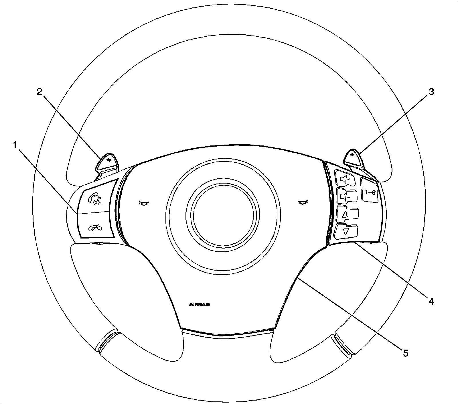
1 - Steering Wheel Control Switch - Left (AAB)
2 - Automatic Transmission Manual Shift Switch - Left (MYC)
3 - Automatic Transmission Manual Shift Switch - Right (MYC)
4 - Steering Wheel Control Switch - Right (UK3)
5 - Inflatable Restraint Steering Wheel Module
Center of Steering Wheel
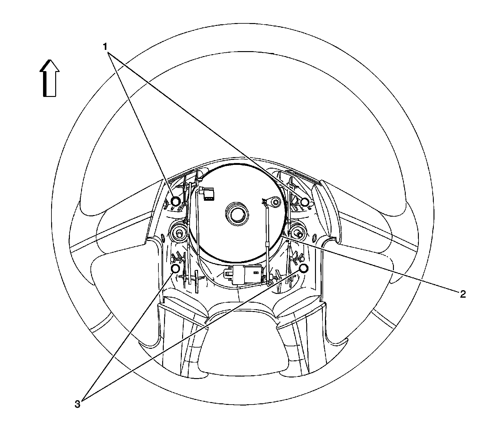
1 - Horn Switch Contacts
2 - Inflatable Restraint Steering Wheel Module Coil
3 - Horn Switch Contacts
Steering Components
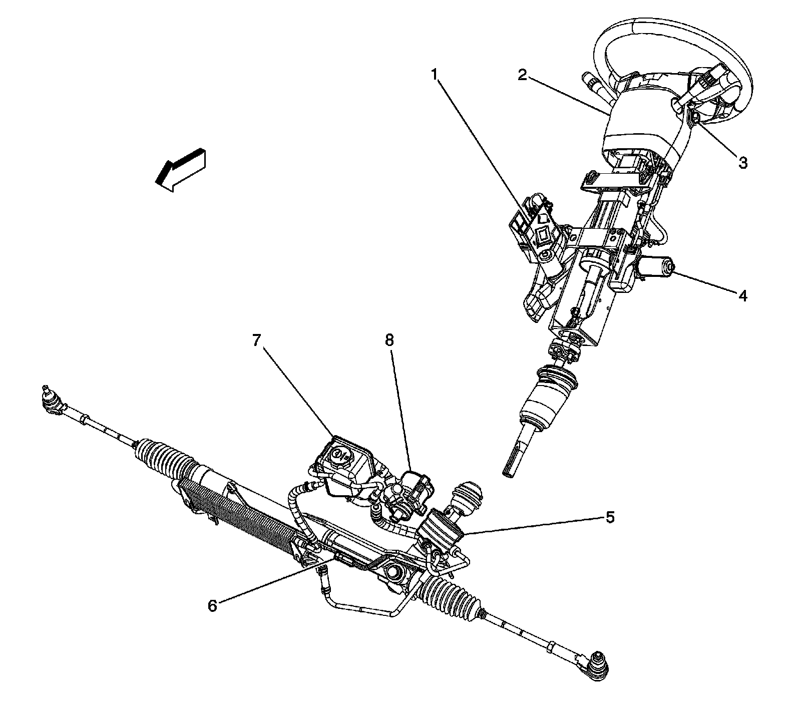
1 - Steering Column Lock Control Module (ULS)
2 - Steering Column Telescope Switch (N37/NP7)
3 - Steering Wheel Tilt Lever
4 - Steering Column Telescope Motor (N37/NP7)
5 - Variable Effort Steering Actuator
6 - Variable Effort Steering Actuator Connector
7 - Power Steering Fluid Reservoir
8 - Power Steering Pump
Steering Column
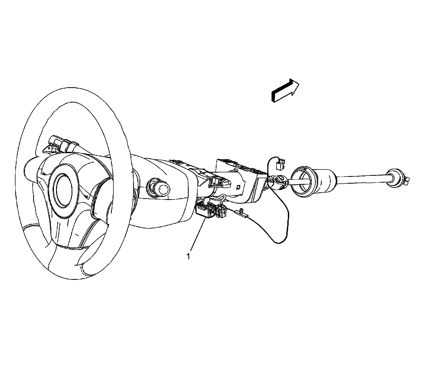
1 - X231
Left Side of Steering Wheel (T79)
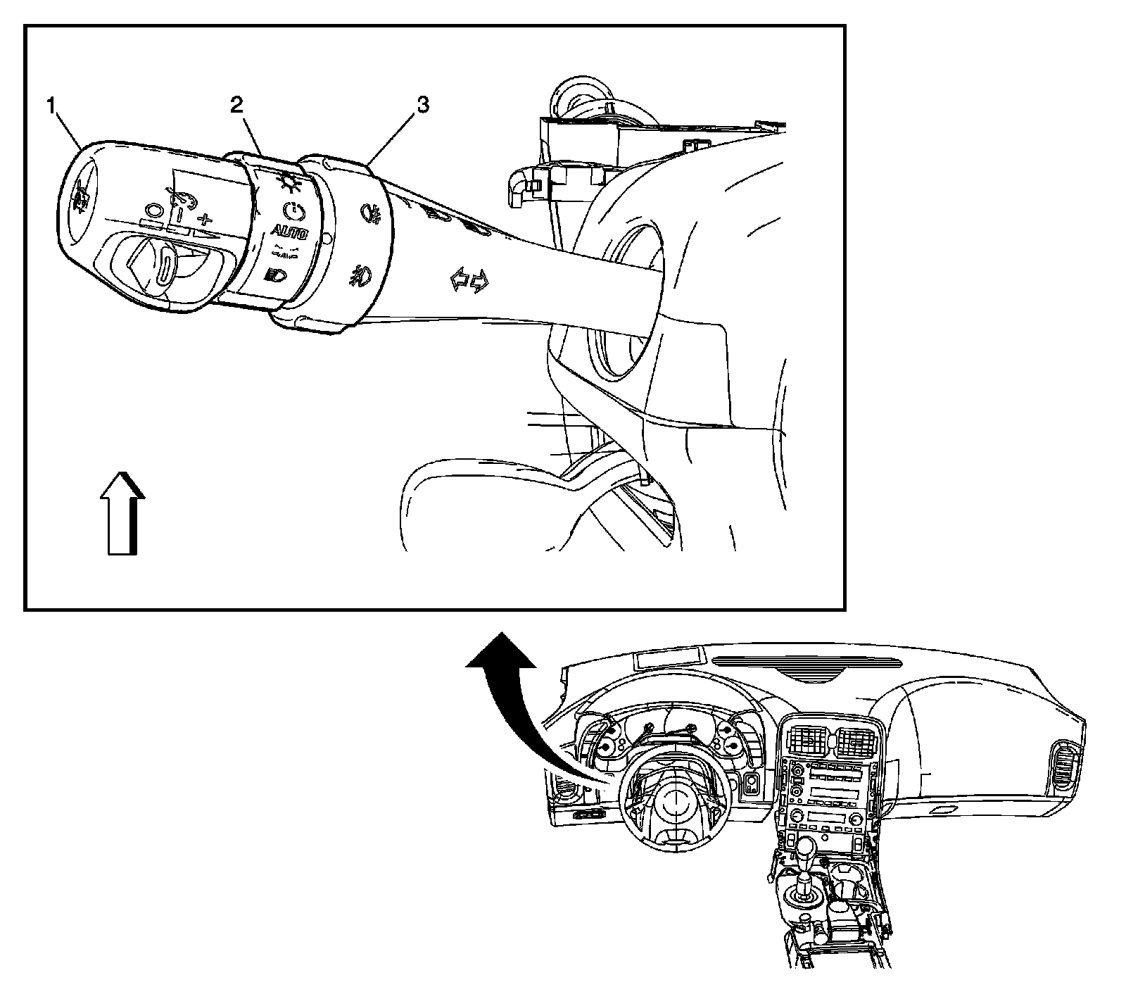
1 - Turn Signal/Multifunction Switch
2 - Headlamp Switch
3 - Fog Lamp Switch
Left Side of Instrument Panel
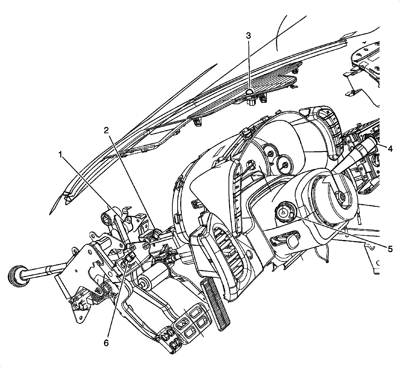
1 - Brake Pedal Position (BPP) Sensor
2 - Accelerator Pedal Position (APP) Sensor
3 - Sunload Sensor
4 - Windshield Washer/Wiper Switch
5 - Turn Signal/Multifunction Switch
6 - Clutch Pedal Position (CPP) Sensor (MM6/MZ6/MN6)
Left Side of I/P (LS7/LS9)
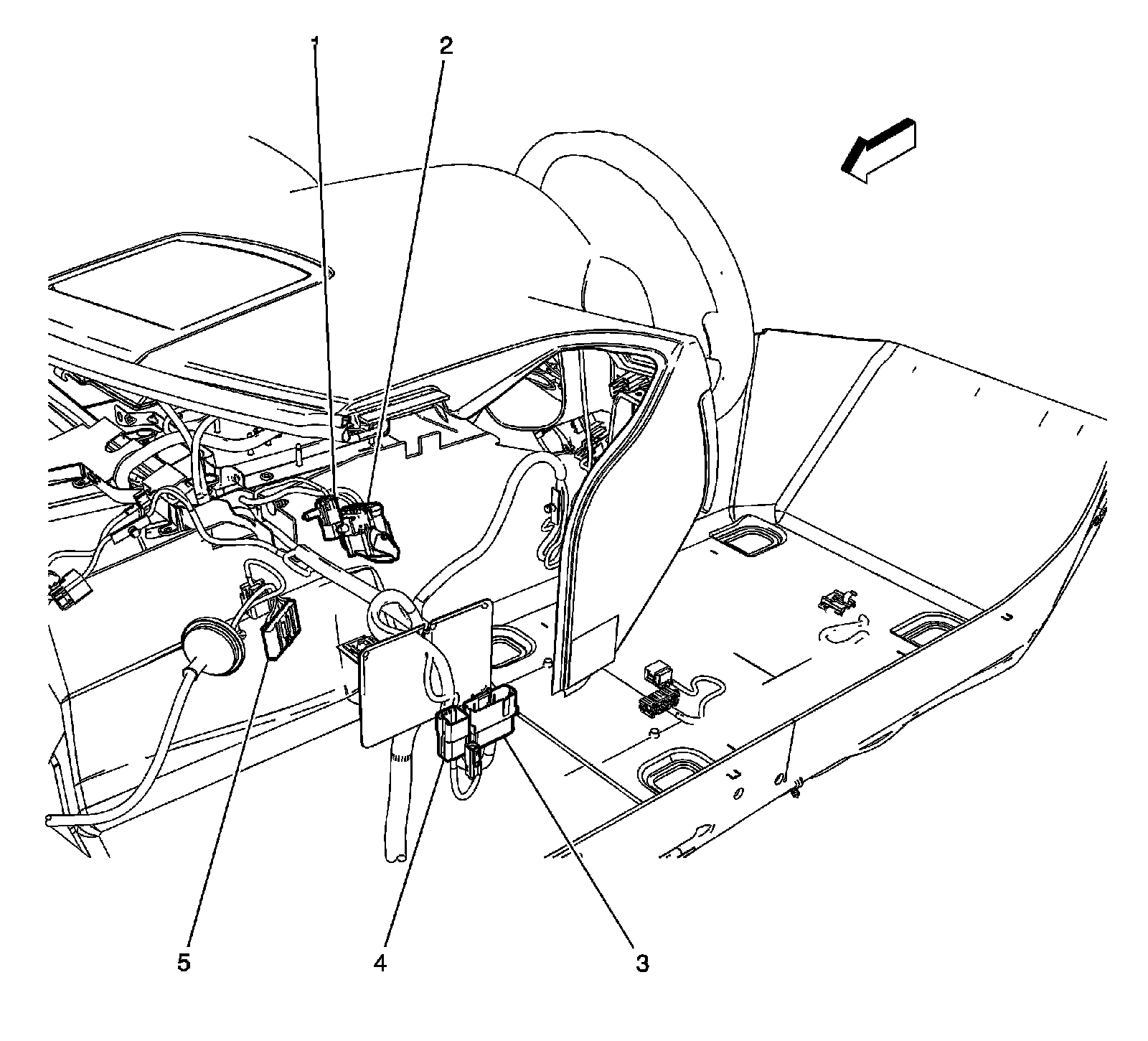
1 - X275
2 - X231
3 - X600
4 - X503
5 - JX205
Passenger Area
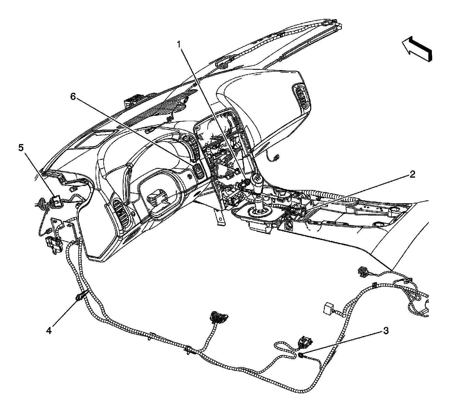
1 - Cigar Lighter
2 - Accessory Power Outlet
3 - G301
4 - G201
5 - JX205
6 - Ignition Mode Switch (IMS)
Under Left Side of the Dash
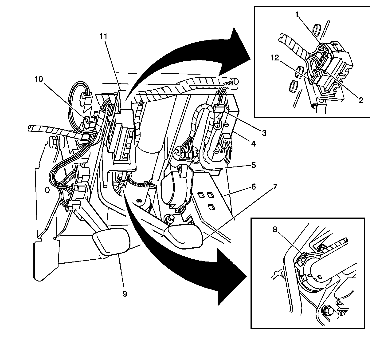
1 - Stop Lamp Switch X1
2 - Stop Lamp Switch X3
3 - X231
4 - Radio X5 (Denso Radio)
5 - Accelerator Pedal Position (APP) Sensor
6 - Accelerator Pedal
7 - Brake Pedal
8 - Steering Wheel Position Sensor
9 - Clutch Pedal (MM6/MZ6/MN6)
10 - Clutch Pedal Position (CPP) Switch (MM6/MZ6/MN6)
11 - Stop Lamp Switch
12 - Stop Lamp Switch Connector X2
Under Steering Column
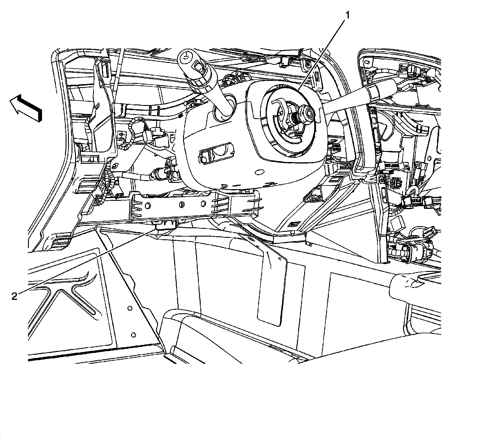
1 - Data Link Connector (DLC)
2 - Inflatable Restraint Steering Wheel Module Coil
Instrument Panel and Overhead Lamps
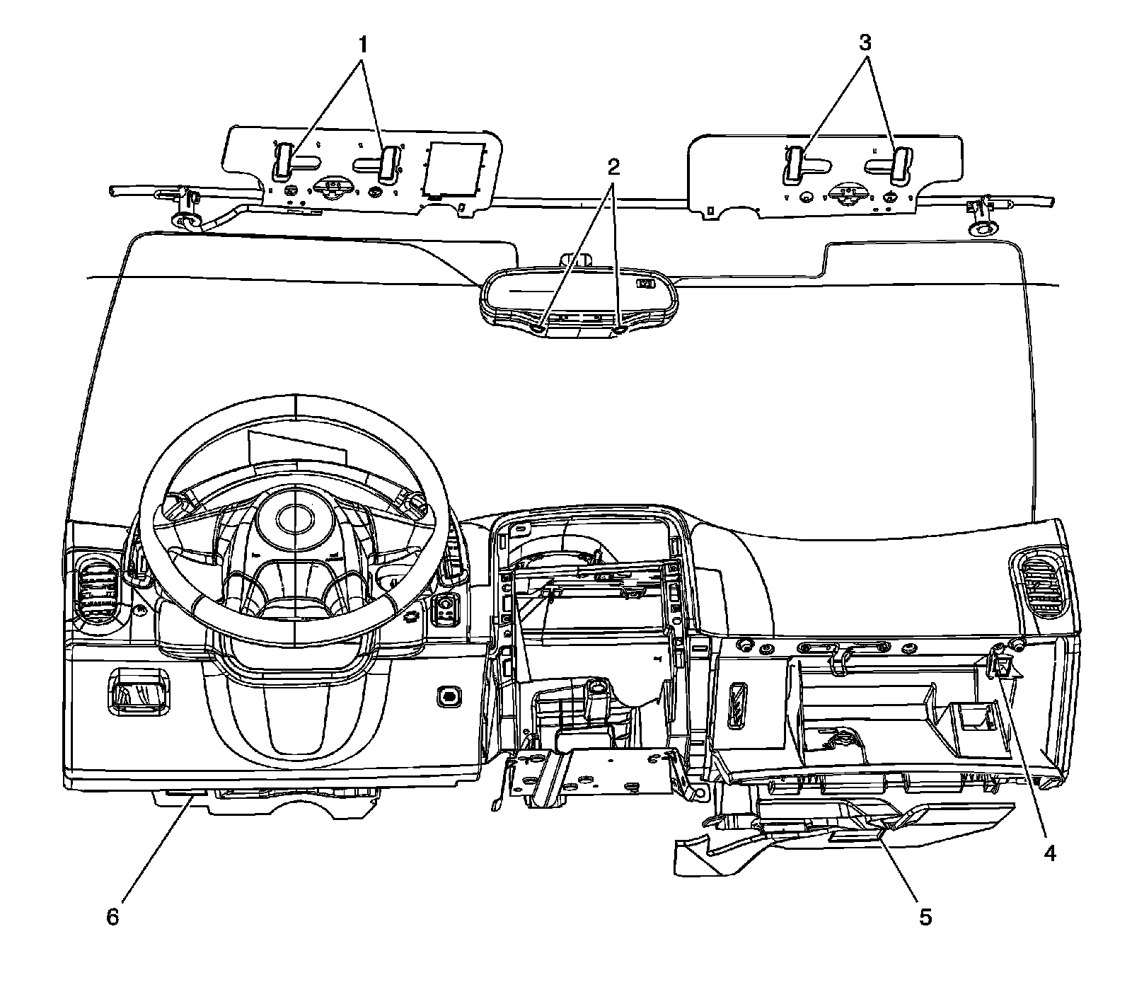
1 - Vanity Mirror Lamp - Left
2 - Courtesy/Reading Lamps - Left Front/Right Front
3 - Vanity Mirror Lamp - Right
4 - I/P Compartment Lamp
5 - I/P Courtesy Lamp - Right
6 - I/P Courtesy Lamp - Left
Cellular Communication Components
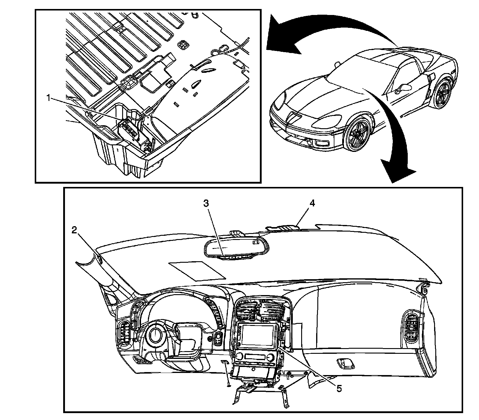
1 - Vehicle Communication Interface Module (VCIM) (UE1)/Traffic Information Receiver (UZD/U3Z)
2 - Cellular Telephone Microphone
3 - Inside Rearview Mirror (ISRVM)
4 - Cellular and Navigation Antenna (UE1)
5 - Radio
Behind the Center of the Instrument Panel
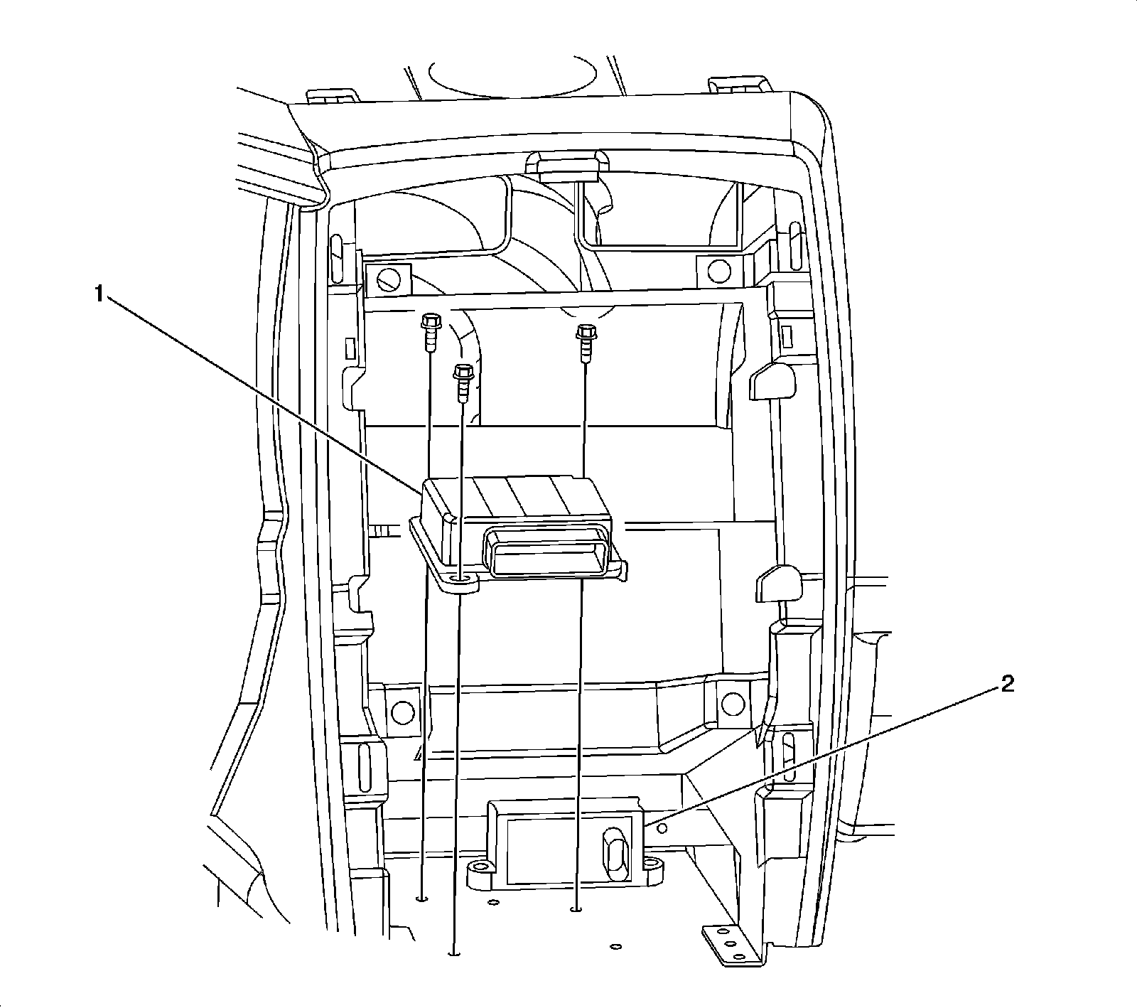
1 - Inflatable Restraint Sensing and Diagnostic Module (SDM)
2 - Yaw and Lateral Accelerometer Sensor
Instrument Panel and Console Components
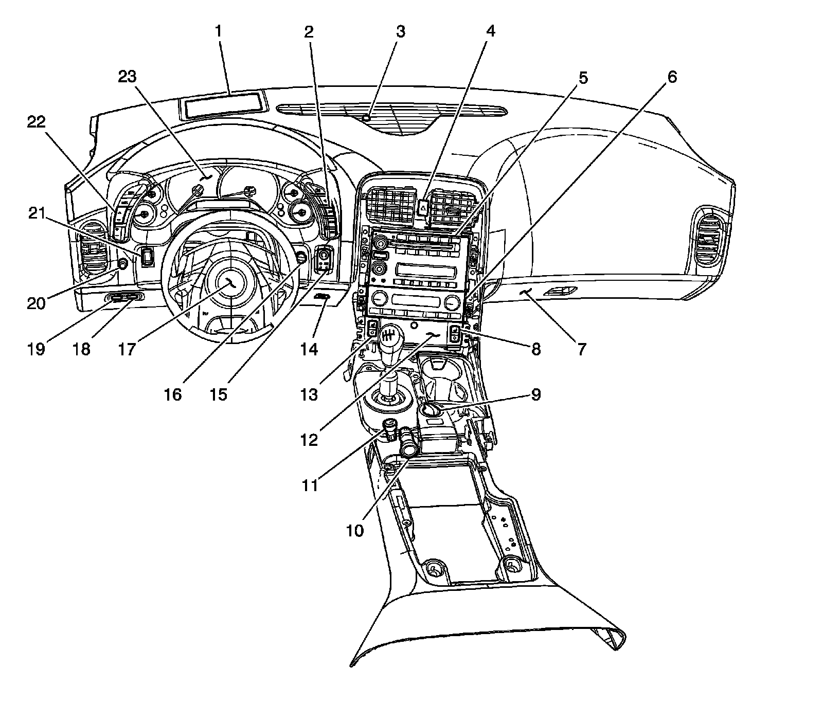
1 - Head Up Display (HUD) (UV6)
2 - Driver Information Center (DIC) Switch
3 - Sunload Sensor
4 - Hazard Warning Switch
5 - Radio
6 - HVAC Control Module
7 - I/P Compartment Lamp - Right
8 - Heated Seat Switch - Passenger (KA1)
9 - Electronic Suspension Control (ESC) Switch
10 - Accessory Power Outlet
11 - Traction Control Switch (TCS)
12 - Cigar Lighter
13 - Heated Seat Switch - Driver (KA1)
14 - I/P Compartment Lamp - Left
15 - Ignition Mode Switch (IMS)
16 - Air Temperature Sensor Assembly - Inside
17 - Inflatable Restraint Steering Wheel Module
18 - Rear Compartment Lid Release Switch - Interior
19 - Fuel Door Release Switch
20 - I/P Dimmer Switch
21 - Folding Top Control Switch (CM7)
22 - Head Up Display (HUD) Switch (UV6)
23 - Instrument Panel Cluster (IPC)
HVAC Module Components
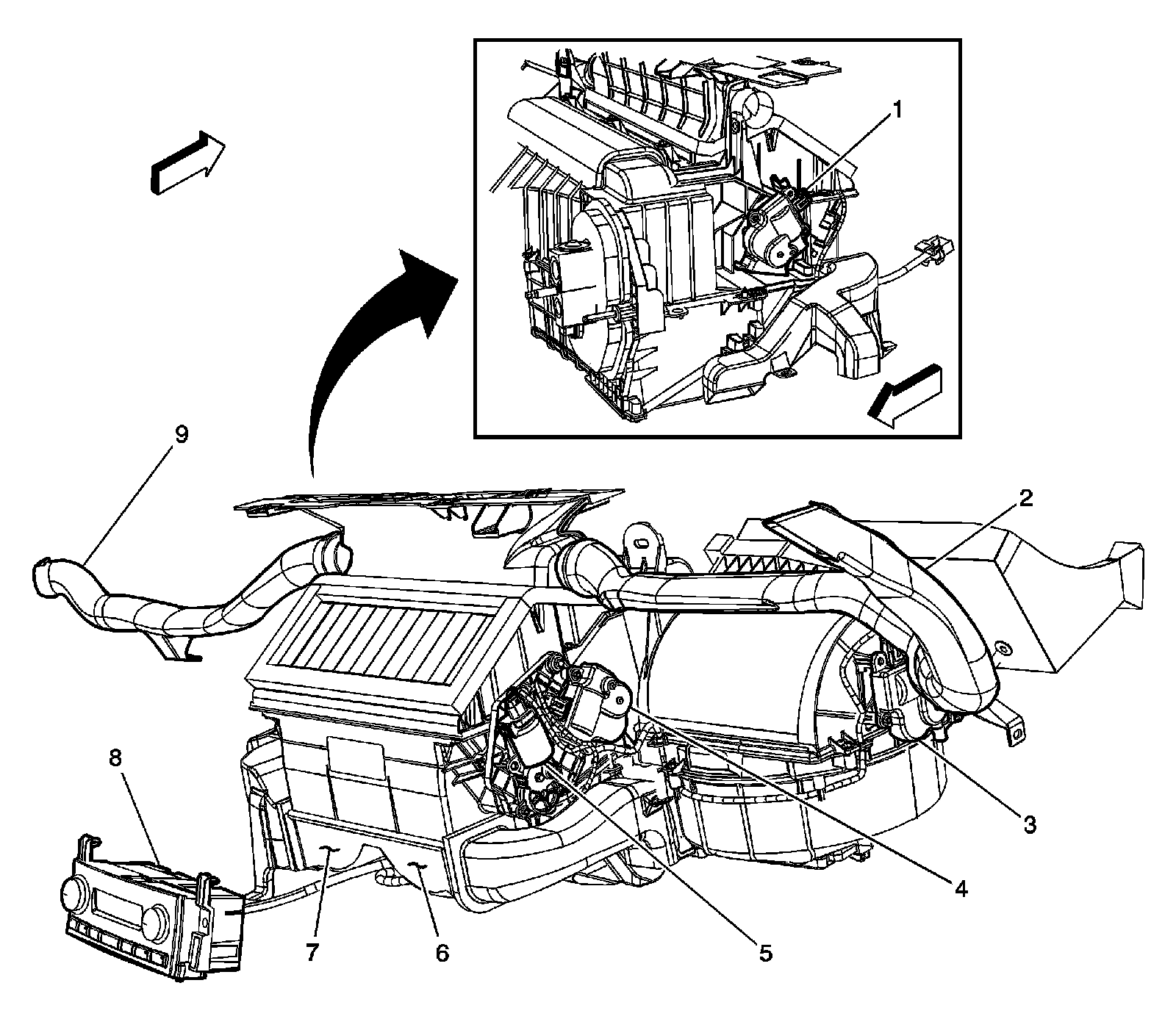
1 - Air Temperature Actuator-Left
2 - Air Temperature Sensor-Upper Right
3 - Recirculation Actuator
4 - Air Temperature Actuator-Right
5 - Mode Actuator
6 - Air Temperature Sensor-Lower Right
7 - Air Temperature Sensor-Lower Left
8 - HVAC Control Module
9 - Air Temperature Sensor-Upper Left
Right Instrument Panel Console
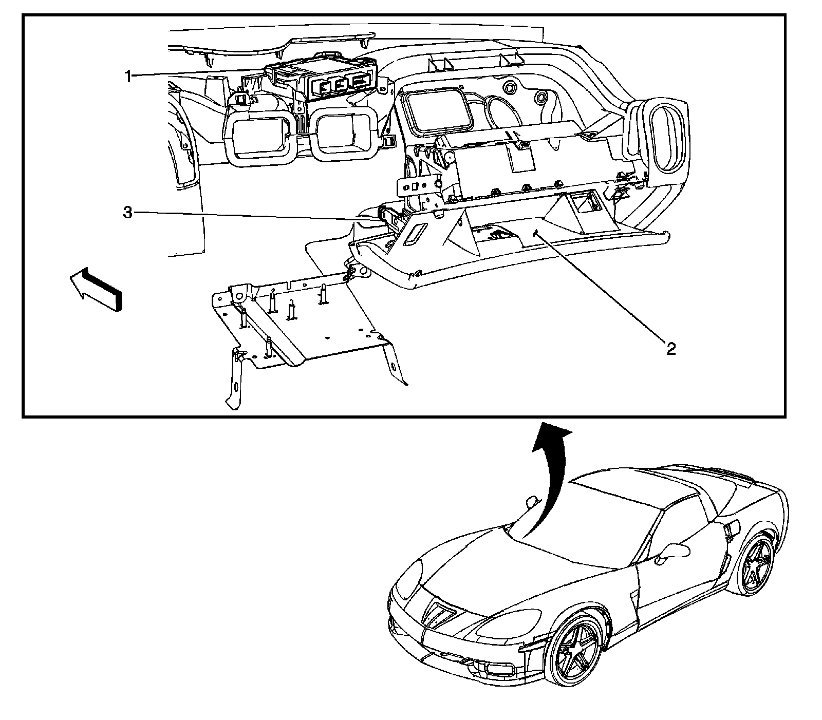
1 - Remote Control Door Lock Receiver (RCDLR)
2 - I/P Compartment
3 - Keyless Entry Antenna - Backup
Instrument Panel Harness - Engine Compartment and Lower Right Side of Instrument Panel
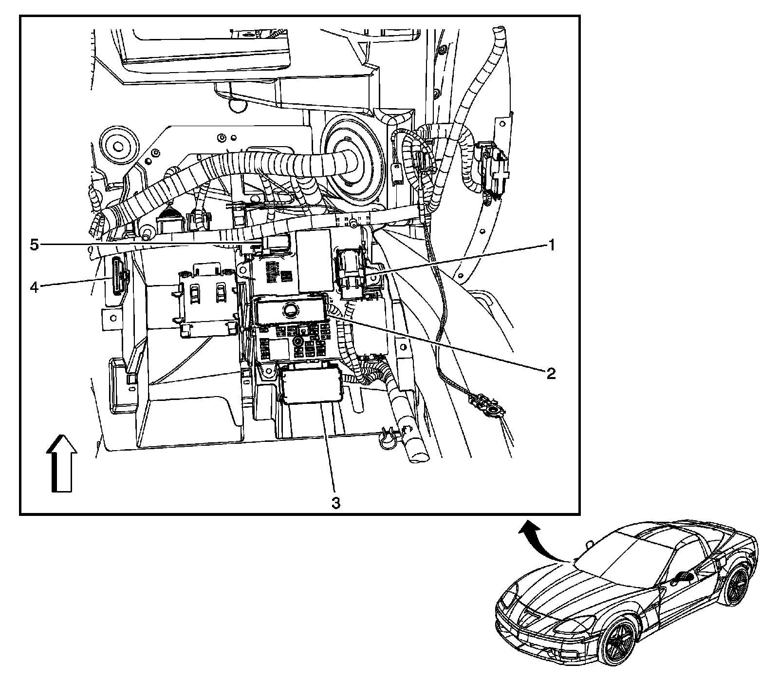
1 - Body Control Module (BCM) X2
2 - Fuse Block - I/P
3 - Relay Block - I/P
4 - JX208
5 - Body Control Module (BCM) X1
Right Side of Instrument Panel
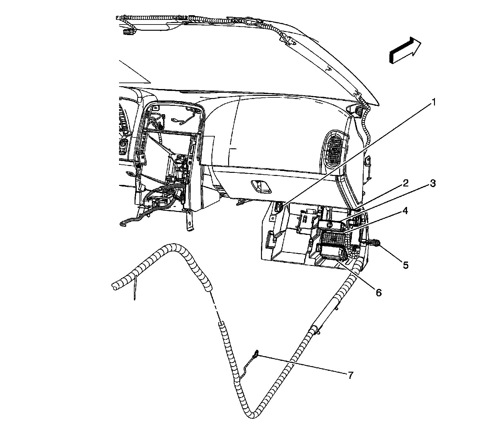
1 - JX208
2 - Body Control Module (BCM) X2
3 - Body Control Module (BCM) X3
4 - Body Control Module (BCM) X4
5 - G202
6 - Relay Block - I/P
7 - G302
Right Side of I/P (LS7/LS9)
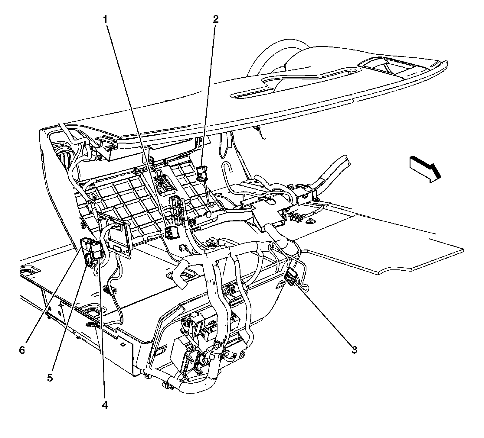
1 - X285 (UL2)
2 - X275
3 - JX208
4 - X602 (U65)
5 - Coaxial Cable
6 - X600
Floor Shift Assembly (MYC)
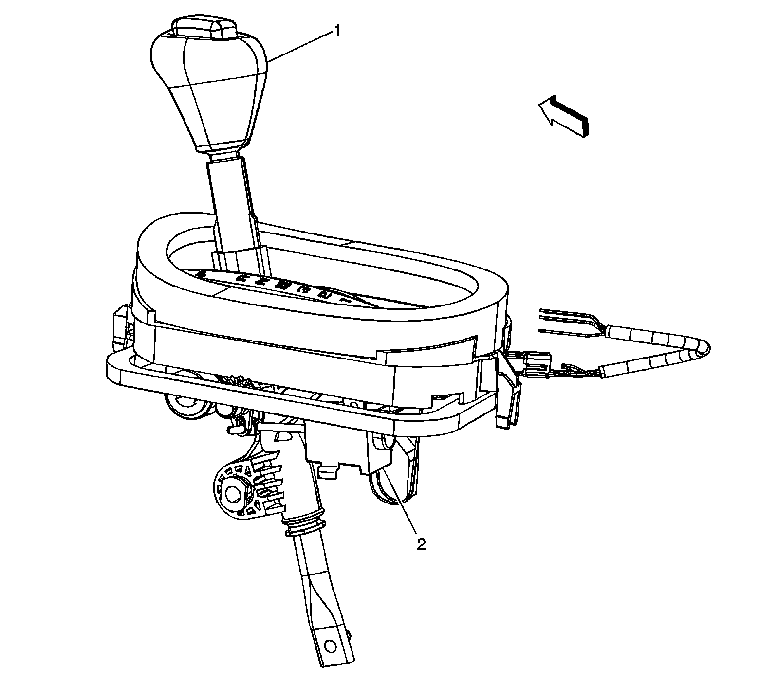
1 - Automatic Transmission Shift Lever
2 - Automatic Transmission Shift Lock Control Solenoid
Factory Service Tools
Use the Manual With the Right Hardware
Pair factory procedures with proven DIY tools so the instructions are easier to execute.
Disclosure: Verified tool recommendations may earn an affiliate commission at no cost to you.
When to See a Mechanic
Stop DIY work and contact a certified mechanic immediately if any of the following apply:
- • You smell fuel, burning insulation, or see smoke.
- • Brakes feel soft, pull hard to one side, or make grinding noises.
- • The engine overheats, stalls repeatedly, or misfires under load.
- • You are missing required tools, torque specs, or safe lifting equipment.
- • You are not confident in the next step or safety outcome.