
Safety Warning
DIY auto repair can cause serious injury, fire, or vehicle damage. These guides are for informational purposes only. Always follow OEM torque specs, wear PPE, and consult a certified mechanic if you are unsure. You are solely responsible for your safety.
2008 Chevrolet Uplander V6-3.9LFACTORY OEM SERVICE PROCEDURE
Auxiliary HVAC Module Replacement
Auxiliary HVAC Module Replacement
Tools Required
* J 39400-A Halogen Leak Detector
* J 38185 Hose Clamp Pliers
Removal Procedure
Important: Cap or tape the open air conditioning (A/C) components immediately in order to prevent system contamination.
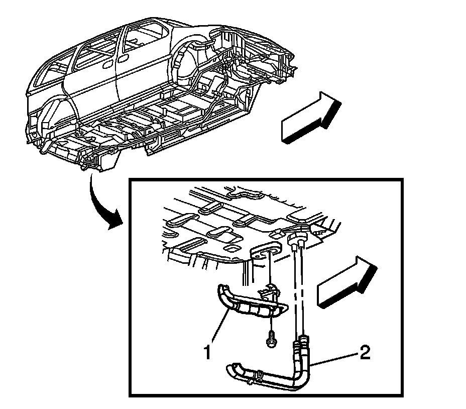
1. Recover the refrigerant. Refer to Refrigerant Recovery and Recharging (Refrigerant Recovery and Recharging).
2. Remove the left rear quarter trim panel.
3. Drain the cooling system. Refer to Cooling System Draining and Filling (Static Fill LZ9) (Service and Repair)Cooling System Draining and Filling (Vac-N-Fill) (Service and Repair).
4. Raise and support the vehicle. Refer to Lifting and Jacking the Vehicle (Service and Repair).
5. Remove the level ride air compressor. Refer to Air Compressor Replacement (Air Compressor Replacement).
6. Remove the auxiliary A/C line block fitting bolt.
7. Remove the A/C line (1) block fitting.
8. Remove and discard the sealing washers.
9. Cap or tape the A/C lines.
10. Disconnect the auxiliary heater hoses (2) from the heater core pipes using the J 38185.
11. Lower the vehicle.
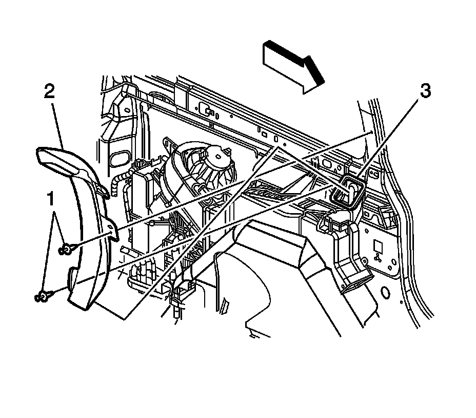
12. Remove the auxiliary A/C outlet pillar duct bolts (1).
13. Remove the auxiliary A/C outlet pillar duct (2).
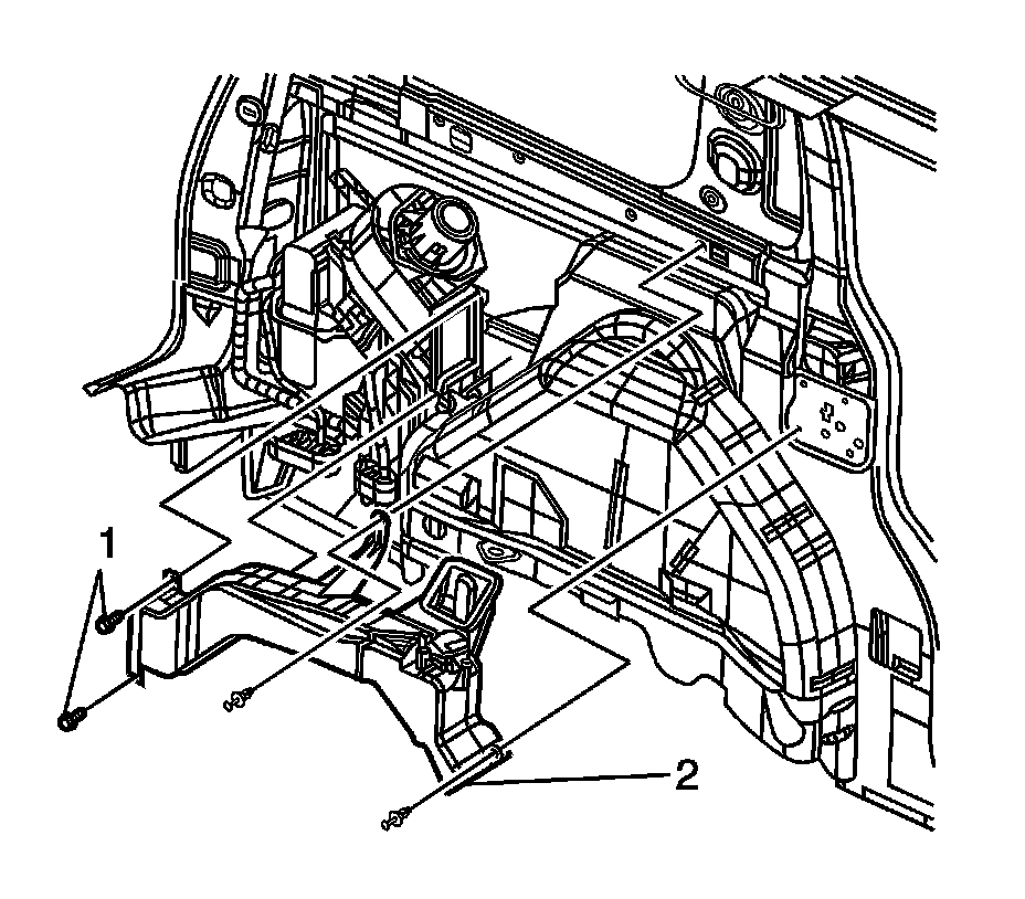
14. Remove the auxiliary A/C outlet duct bolts (1).
15. Remove the auxiliary A/C outlet duct (2).
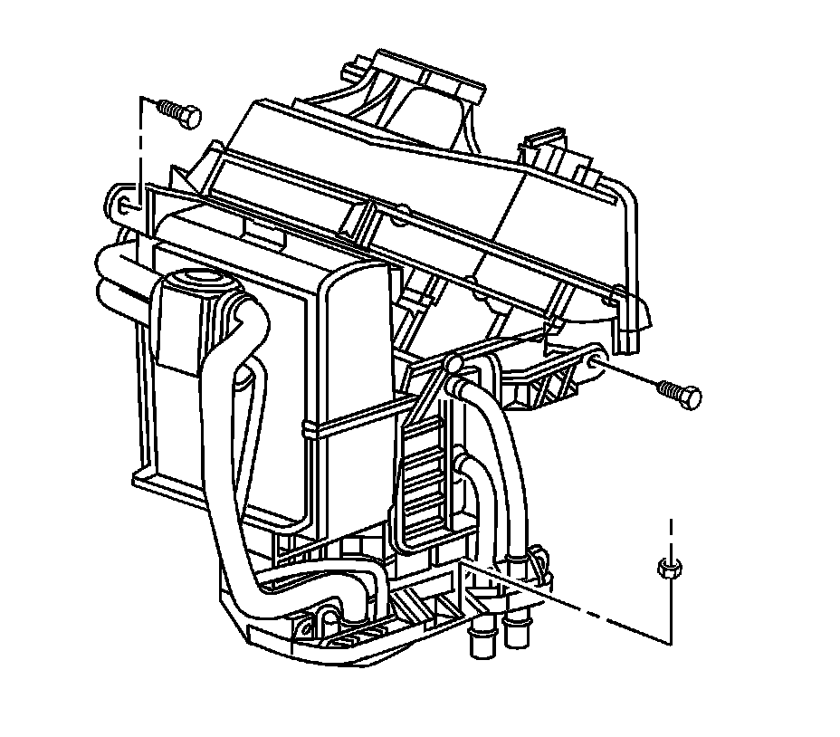
16. Disconnect the auxiliary blower motor electrical connector.
17. Disconnect the auxiliary blower motor resistor electrical connector.
18. Disconnect the auxiliary temperature actuator electrical connector.
19. Remove the HVAC module assembly bolts and nut.
20. Remove the left power sliding door (PSD) module from the mounting bracket and reposition aside, if equipped.
21. Remove the HVAC module assembly from the vehicle.
22. Remove and discard the HVAC module assembly to body seals.
Installation Procedure
1. Install new HVAC module assembly to body seals.
2. Install the HVAC module assembly to the vehicle.
Notice: Refer to Fastener Notice (Fastener Notice).
3. Install the HVAC module assembly bolts and the nut.
Tighten the bolts/nut to 10 N.m (89 lb in).
4. Install the left PSD module to the mounting bracket.
5. Connect the auxiliary temperature actuator electrical connector.
6. Connect the electrical connector to the auxiliary blower motor resistor.
7. Connect the auxiliary blower motor electrical connector.
8. Install the auxiliary A/C outlet duct (2).
9. Install the auxiliary A/C outlet duct bolts (1).
Tighten the bolts to 10 N.m (89 lb in).
10. Install the auxiliary A/C outlet pillar duct (2).
11. Install the auxiliary A/C outlet pillar duct bolts (1).
Tighten the bolts to 10 N.m (89 lb in).
12. Raise and suitably support the vehicle.
13. Connect the auxiliary heater hoses (2) to the heater core pipes.
14. Remove the cap or tape from the A/C lines.
15. Install the new sealing washers onto the A/C line. Refer to Sealing Washer Replacement (Sealing Washer Replacement).
16. Install the auxiliary A/C line (1) block fitting bolt.
Tighten the bolt to 20 N.m (15 lb ft).
17. Install the level ride air compressor. Refer to Air Compressor Replacement (Air Compressor Replacement).
18. Lower the vehicle.
19. Fill the cooling system. Refer to Cooling System Draining and Filling (Static Fill LZ9) (Service and Repair)Cooling System Draining and Filling (Vac-N-Fill) (Service and Repair).
20. Evacuate and recharge the A/C system. Refer to Refrigerant Recovery and Recharging (Refrigerant Recovery and Recharging).
21. Leak test the fittings of the component usingJ 39400-A.
22. Install the left rear quarter trim panel.
23. Refer to Control Module References (Programming and Relearning) for programming and setup information.
Factory Service Tools
Use the Manual With the Right Hardware
Pair factory procedures with proven DIY tools so the instructions are easier to execute.
Disclosure: Verified tool recommendations may earn an affiliate commission at no cost to you.
When to See a Mechanic
Stop DIY work and contact a certified mechanic immediately if any of the following apply:
- • You smell fuel, burning insulation, or see smoke.
- • Brakes feel soft, pull hard to one side, or make grinding noises.
- • The engine overheats, stalls repeatedly, or misfires under load.
- • You are missing required tools, torque specs, or safe lifting equipment.
- • You are not confident in the next step or safety outcome.