
Safety Warning
DIY auto repair can cause serious injury, fire, or vehicle damage. These guides are for informational purposes only. Always follow OEM torque specs, wear PPE, and consult a certified mechanic if you are unsure. You are solely responsible for your safety.
2008 Chevrolet Uplander V6-3.9LFACTORY OEM SERVICE PROCEDURE
Internal Components
Disassembled Views
Internal Components (1 of 2)
Internal Components:
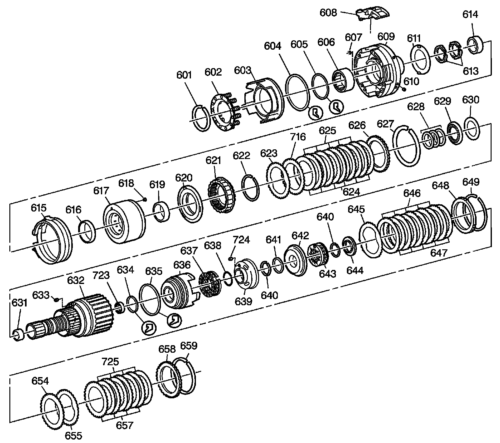
601 - 4th Clutch Spring Retaining Ring
602 - 4th Clutch Piston Return Spring Assembly
603 - 4th Clutch Piston Assembly
604 - 4th Clutch Piston Seal Outer
605 - 4th Clutch Piston Seal Inner
606 - Drawn Cup Bearing Assembly
607 - Orificed Cup Plug
608 - Drive Link Lube Scoop
609 - Driven Sprocket Support Assembly
610 - Cup Plug
611 - Thrust Washer Driven Sprocket Support 2nd Clutch Drum
613 - Oil Seal Ring
614 - Driven Sprocket Support Bushing
615 - Reverse Band Assembly
616 - 75.5 OD X 8.0 Bushing
617 - 2nd Clutch Housing
618 - Check Valve Retainer and Ball Assembly 2nd Clutch
619 - 70.0 OD X 11.0 Bushing
620 - 2nd Clutch Piston w/Molded Seal
621 - 2nd Clutch Apply Ring and Release Spring Assembly
622 - Retaining Ring
623 - 2nd Clutch Plate Waved
624 - 2nd Clutch Plate Assembly Fiber
625 - 2nd Clutch Reaction Plate Steel
626 - Backing Support Ring Plate Steel
627 - 2nd Clutch Retaining Ring Outer
628 - Oil Seal Ring Input Shaft
629 - Thrust Bearing Support Sprocket/Thrust Washer
630 - Selective Thrust Washer Bearing/Input Clutch Hub
631 - Input Shaft Bushing
632 - Input Housing Sleeve and Shaft Assembly
633 - Check Valve Retainer and Ball Assembly
634 - Input Clutch Piston Seal Inner
635 - Input Clutch Piston Seal Outer
636 - Input Clutch Piston
637 - Input Clutch Spring and Retainer Assembly
638 - O-Ring Seal
639 - 3rd Clutch Piston Housing
640 - Retaining Ring 3rd Clutch Piston Housing/Input Shaft
640 - Retaining Ring 3rd Clutch Piston Housing/Input Shaft
641 - 3rd Clutch Piston Seal Inner
642 - 3rd Clutch Piston and Seal Assembly
643 - 3rd Clutch Spring Retainer and Guide Assembly
644 - Thrust Bearing Assembly
645 - 3rd Clutch Plate Waved
646 - 3rd Clutch Plate Assembly OD Spline
647 - 3rd Clutch Plate Assembly ID Spline
648 - 3rd Clutch Backing Plate
649 - 3rd Clutch Backing Plate Retaining Ring
654 - Input Clutch Apply Plate
655 - Input Clutch Plate Waved
657 - Input Clutch Plate Steel
657 - Input Clutch Plate Steel
658 - Input Clutch Backing Plate Steel
659 - Input Clutch Backing Plate Retaining Ring
716 - 2nd Clutch Apply Reaction Plate Tapered
723 - 4th Clutch Shaft to Input Housing Bearing
724 - 3rd Clutch Piston Housing Ball Check Valve Assembly
725 - Input Clutch Plate Assembly Fiber - Pawl Clutch
Internal Components (2 of 2)
Internal Components:
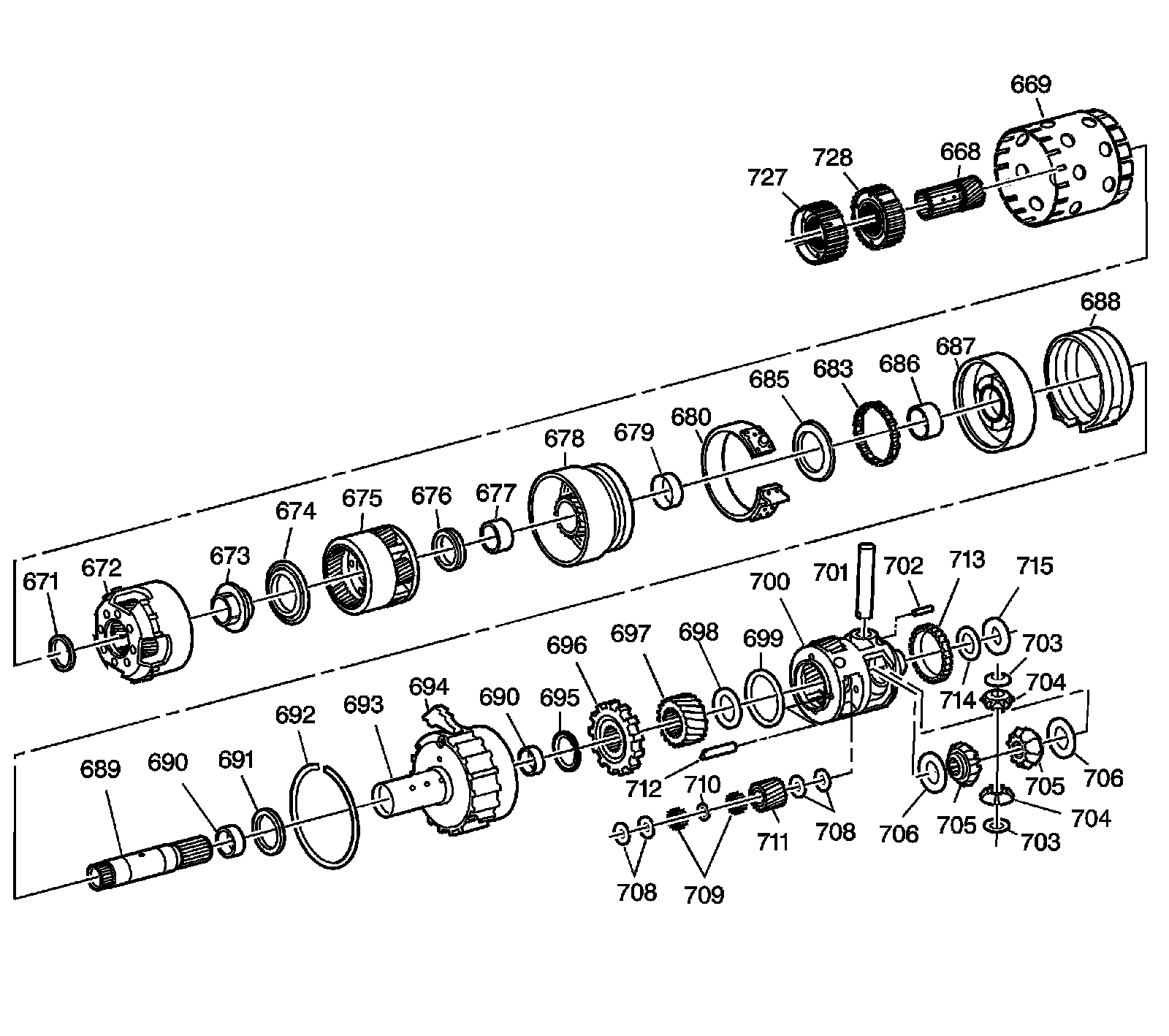
668 - Input Sun Gear
669 - Reverse Reaction Drum
671 - Input Sun Gear Thrust Bearing Assembly
672 - Input Complete Carrier Assembly
673 - Input Carrier/Reaction Carrier Lube Dam
674 - Input/Reaction Carrier Thrust Bearing Assembly
675 - Reaction Complete Carrier Assembly
676 - Reaction Carrier/Sun Gear Thrust Bearing Assembly
677 - Left Hand Reaction Sun Gear Bushing
678 - Reaction Sun/Drum Gear Assembly
679 - Right Hand Reaction Sun Gear Bushing
680 - 2/1 Manual Band Assembly
683 - 1/2 Support Roller Clutch Assembly
685 - Thrust Bearing Assembly
686 - 1/2 Support Bushing
687 - 1/2 Support and Drum
688 - Forward Band Assembly
689 - Final Drive Sun Gear Shaft
690 - Final Drive Internal Gear Bushing
690 - Final Drive Internal Gear Bushing
691 - Bearing 1/2 Support/Internal Gear
692 - Retaining Ring Final Drive Internal Gear
693 - Final Drive Internal Gear
694 - Park Pawl Assembly
695 - Thrust Bearing Assembly Internal Gear/Parking Gear
696 - Parking Gear
697 - Final Drive Sun Gear
698 - Carrier/Sun Gear Thrust Bearing Assembly
699 - Spiral Pinion Gear Pin Retaining Ring
700 - Differential/Final Drive Carrier Assembly
701 - Differential Pinion Shaft
702 - Differential Pinion Shaft Retaining Pin
703 - Thrust Washer Differential Pinion
703 - Thrust Washer Differential Pinion
704 - Differential Pinon Gear
704 - Differential Pinon Gear
705 - Differential Side Gear MN7 has unique left/right gears
705 - Differential Side Gear MN7 has unique left/right gears
706 - Bronze Thrust Washer Differential Side Gear
706 - Bronze Thrust Washer Differential Side Gear
708 - Pinion Thrust Washer Steel
708 - Pinion Thrust Washer Steel
709 - Roller Needle Bearing
710 - Pinion Needle Bearing Spacer
711 - Final Drive Planetary Pinion Gear
712 - Planetary Pinion Gear Pin
713 - Vehicle Speed Sensor Reluctor Wheel
714 - Differential Carrier/Case Washer Thrust
715 - Thrust Bearing Assembly
727 - 3rd Clutch Pawl Assembly
728 - Input Clutch Pawl Assembly
Manual Shaft and Parking System Assembly
Manual Shaft and Parking System Assembly:
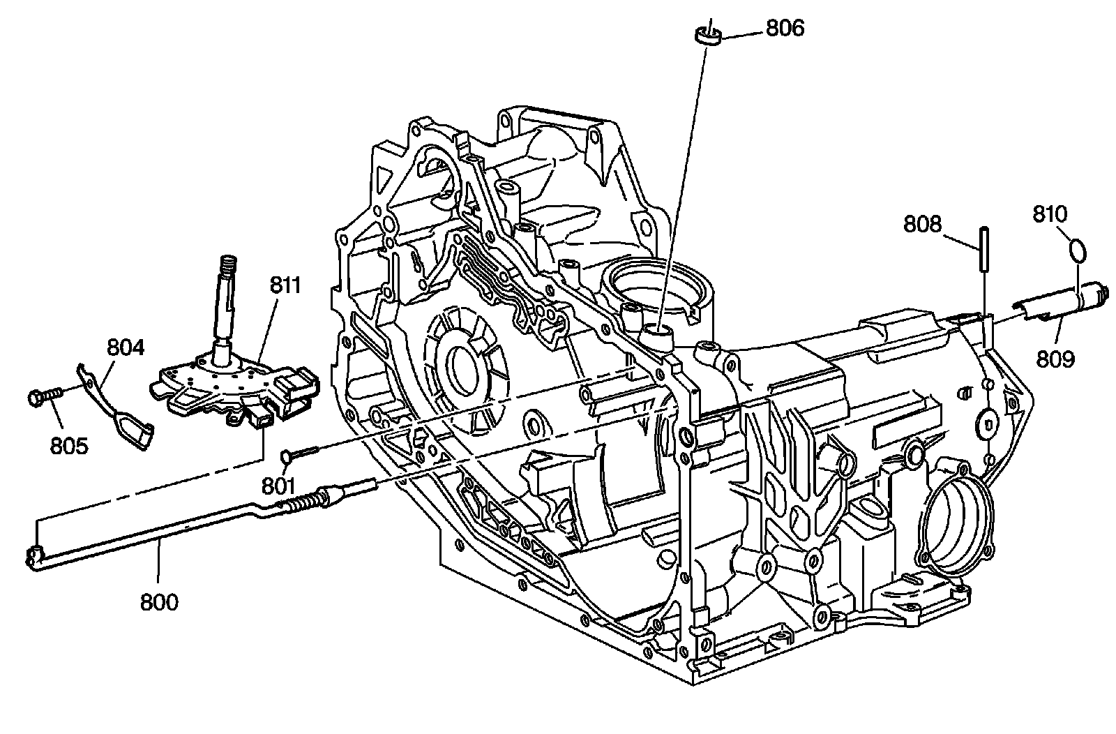
800 - Park Pawl Actuator Assembly
801 - Manual Shift Shaft Pin
804 - Manual Shift Detent Assembly
805 - Manual Shift Detent Bolt/Screw
806 - Manual Shift Shaft Seal Assembly
808 - Park Pawl Actuator Guide Pin
809 - Park Pawl Actuator Guide
810 - Park Pawl Actuator Guide O-Ring Seal
811 - Lever Assembly-Manual Shaft Detent with Internal Mode Switch (IMS)
Factory Service Tools
Use the Manual With the Right Hardware
Pair factory procedures with proven DIY tools so the instructions are easier to execute.
Disclosure: Verified tool recommendations may earn an affiliate commission at no cost to you.
When to See a Mechanic
Stop DIY work and contact a certified mechanic immediately if any of the following apply:
- • You smell fuel, burning insulation, or see smoke.
- • Brakes feel soft, pull hard to one side, or make grinding noises.
- • The engine overheats, stalls repeatedly, or misfires under load.
- • You are missing required tools, torque specs, or safe lifting equipment.
- • You are not confident in the next step or safety outcome.