
Safety Warning
DIY auto repair can cause serious injury, fire, or vehicle damage. These guides are for informational purposes only. Always follow OEM torque specs, wear PPE, and consult a certified mechanic if you are unsure. You are solely responsible for your safety.
2008 Chevrolet Malibu Classic V6-3.5LFACTORY OEM SERVICE PROCEDURE
Passenger Compartment/Roof Component Views
Passenger Compartment/Roof Component Views
Headliner Forward Overhead Components
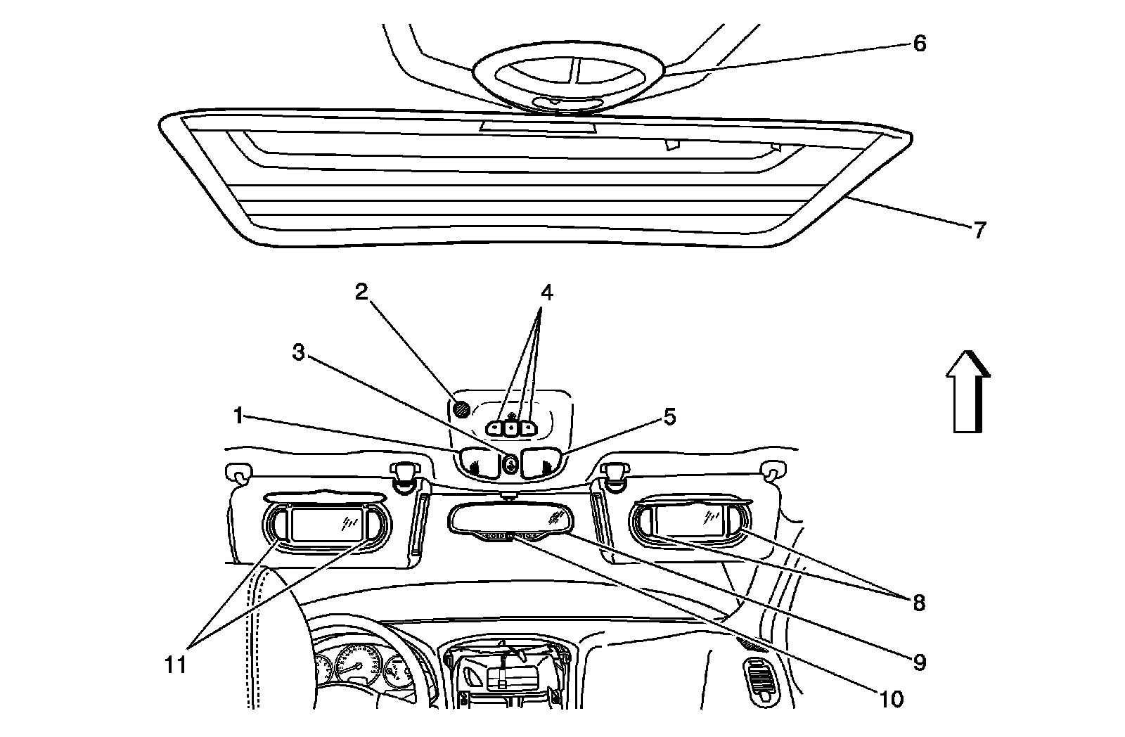
1 - Courtesy/Reading Lamps - Front, Left Reading
2 - Cellular Telephone Microphone (UE1)
3 - Sunroof Switch (CF5)
4 - Garage Door Opener Transmitter (UG1)
5 - Courtesy/Reading Lamps - Front, Right Reading
6 - Dome/Reading Lamp
7 - Sunroof (CF5)
8 - Vanity Mirror Lamp - Right (DH6)
9 - Inside Rearview Mirror
10 - OnStar Keypad (UE1)
11 - Vanity Mirror Lamp - Left (DH6/D74)
Inflatable Restraint Seat Belt Pretensioner - Right Front

1 - Inflatable Restraint Seat Belt Pretensioner - Right Front
Sunroof Components (CF5)
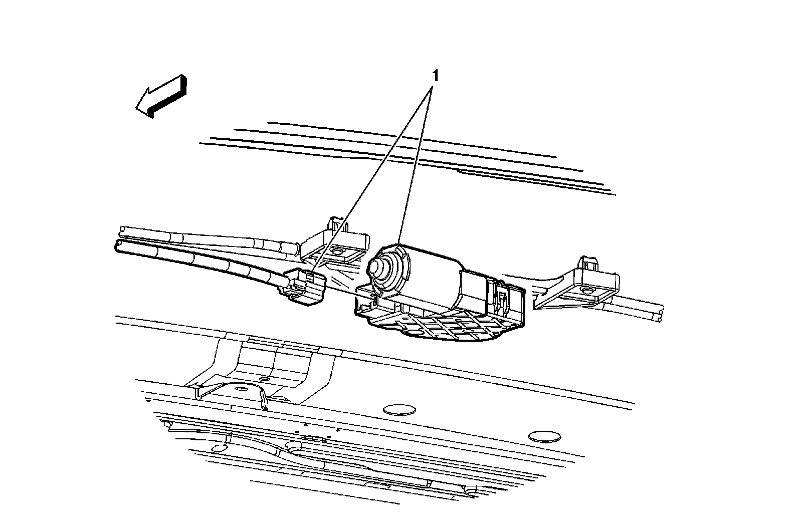
1 - Sunroof Control Module
Under Driver Seat Components
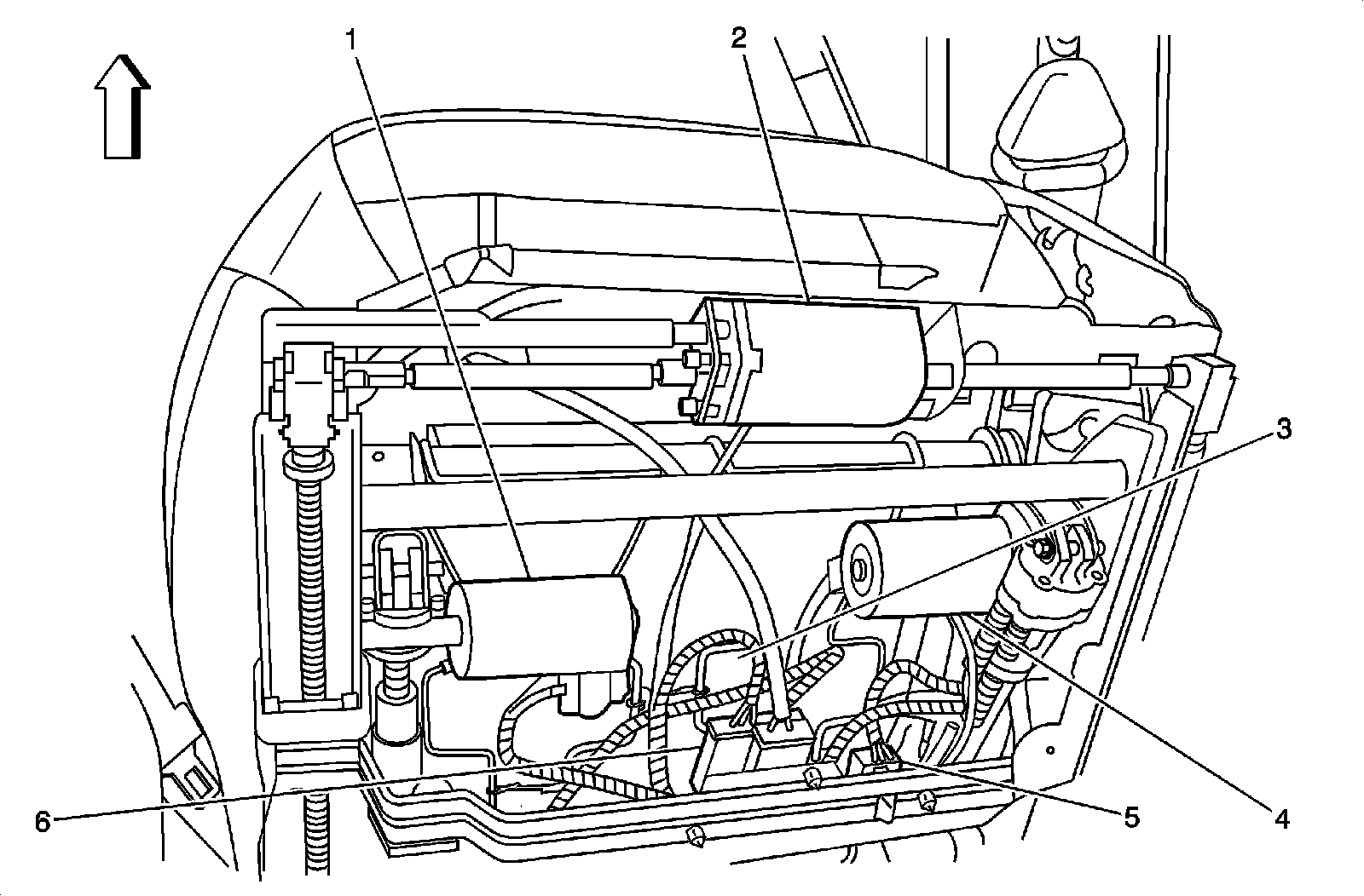
1 - Seat Front Vertical Motor (AG1)
2 - Seat Horizontal Motor (AG1)
3 - Heated Seat Cushion Temperature Sensor - Driver (KA1)
4 - Seat Rear Vertical Motor (AG1)
5 - X300
6 - Heated Seat Control Module - Driver (KA1)
Front Passenger Seat Components
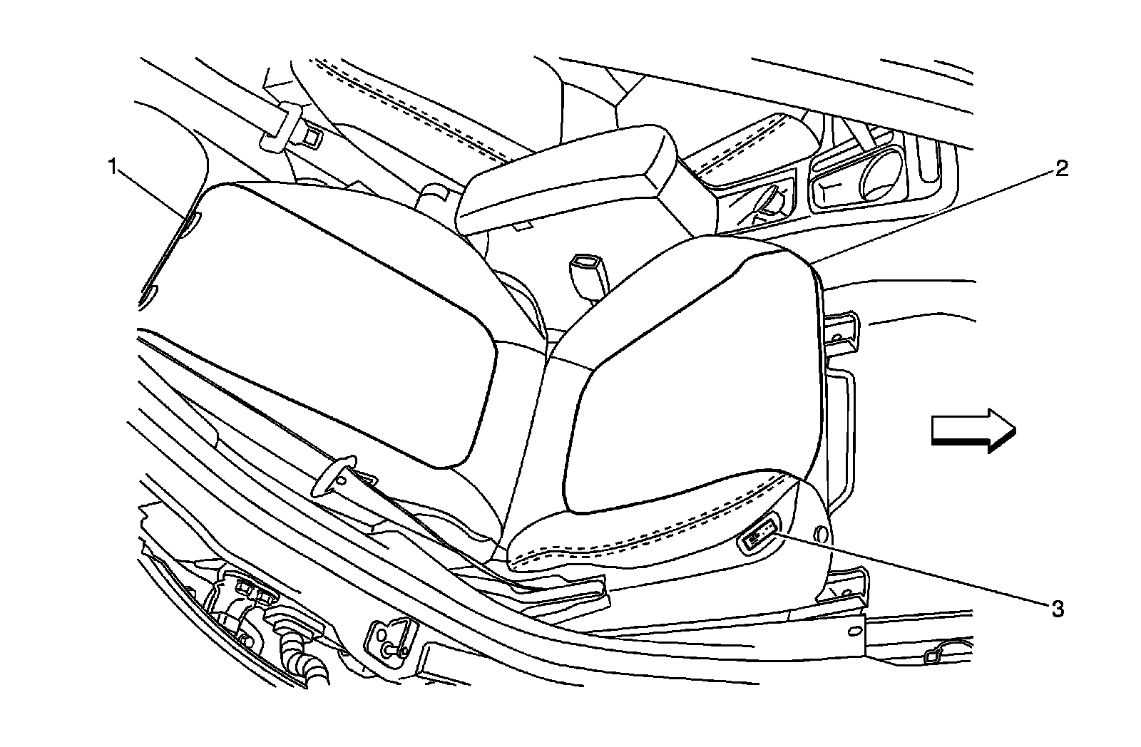
1 - Heated Seat Element - Passenger Back
2 - Heated Seat Element - Passenger Cushion
3 - Heated Seat Switch - Passenger
Radio Antenna Amplifier Module and Radio Rear Window Antenna
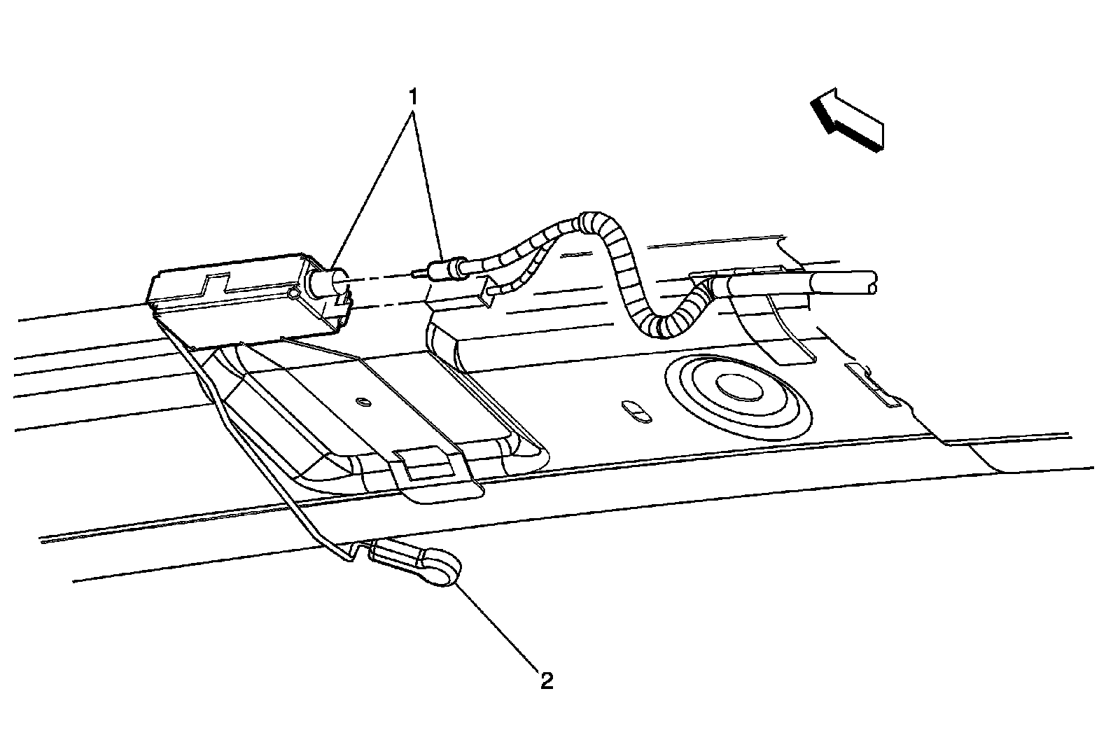
1 - Radio Antenna Amplifier Module
2 - Radio Rear Window Antenna
Inflatable Restraint Seat Belt Pretensioner - Left Front
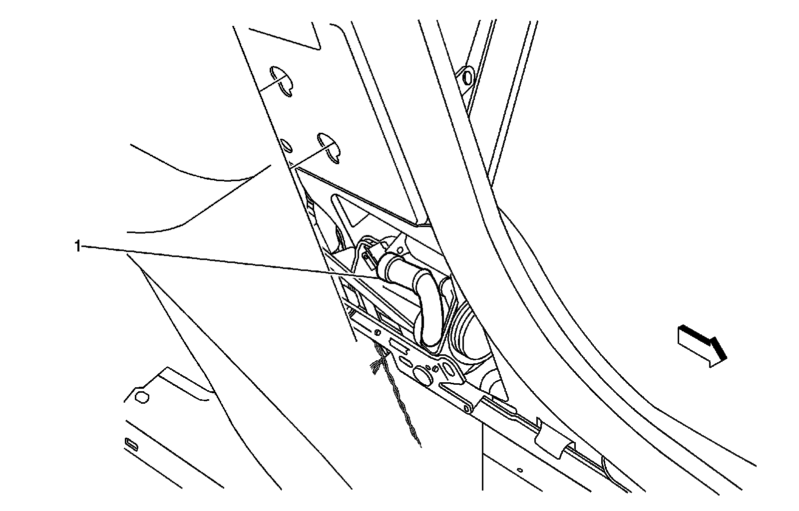
1 - Inflatable Restraint Seat Belt Pretensioner - Left Front
Inflatable Restraint Side Impact Module Components (AY0)
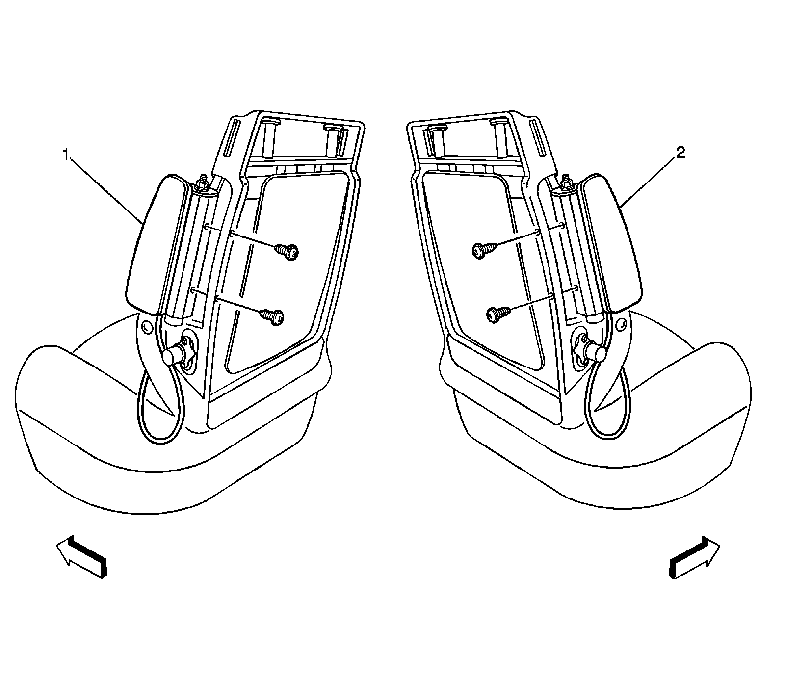
1 - Inflatable Restraint Side Impact Module - Left (AY0)
2 - Inflatable Restraint Side Impact Module - Right (AY0)
Driver Seat Components
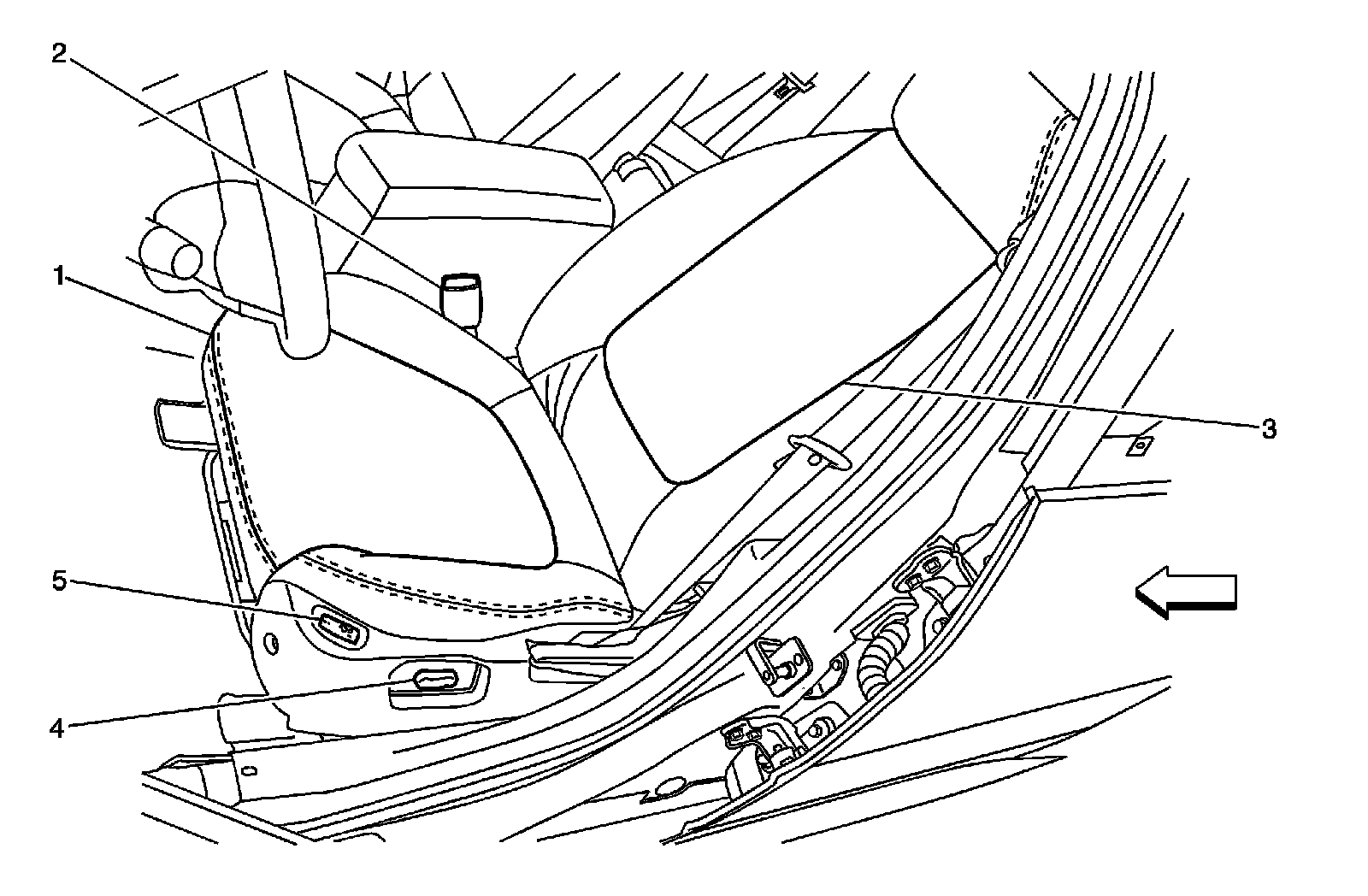
1 - Heated Seat Element - Driver Cushion (KA1)
2 - Seat Belt Switch
3 - Heated Seat Element - Driver Back (KA1)
4 - Seat Adjuster Switch - Driver (AG1/ASN)
5 - Heated Seat Switch - Driver (KA1)
Under Passenger Seat Components
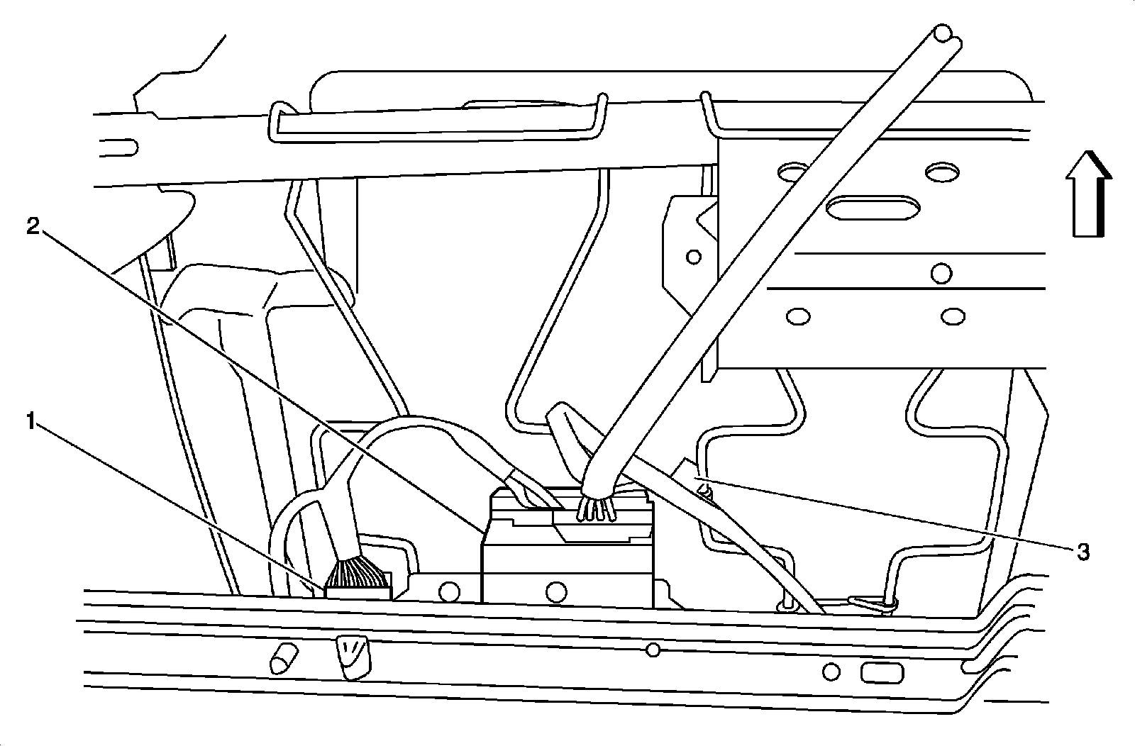
1 - X310
2 - Heated Seat Control Module - Passenger
3 - Heated Seat Cushion Temperature Sensor - Passenger
Inflatable Restraint Side Impact Sensor Components
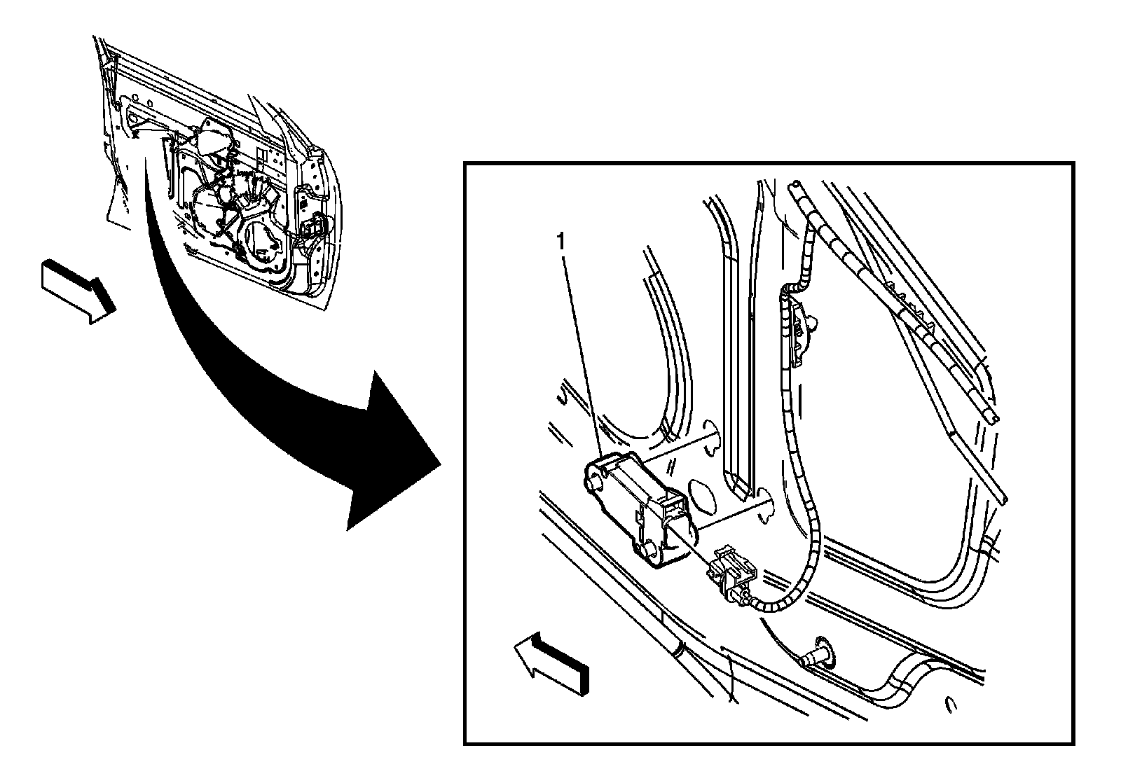
1 - Inflatable Restraint Side Impact Sensor - Left (Right Similar)
SIR Identification Views
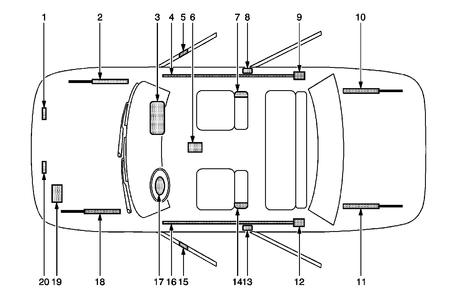
1 - Front End Sensor-Located under the hood at the front right side of the vehicle
2 - Front Hood Assist Rod-A gas shock located under the front hood on the passenger side
3 - Instrument Panel Air Bag-Located at the top right under the instrument panel
4 - Roof Rail Air Bag-Located under the headliner, extending from the passenger front windshield pillar to the passenger rear windshield pillar
5 - Side Impact Sensor (SIS)-Located behind door panel on the passenger front door
6 - Sensing and Diagnostic Module (SDM)-Located underneath the vehicle carpet under the center console
7 - Right Front Side Impact Air Bag-Located on the seat back of passenger seat
8 - Seat Belt Retractor Pretensioner-Located under the trim near the bottom of the center pillar on the passenger side of vehicle
9 - Inflator Module for Roof Rail Air Bag-Located behind the garnish molding on the upper rear pillar
10 - Rear Hood Assist Rod-A gas shock located under the rear truck lid on the passenger side
11 - Rear Hood Assist Rod-A gas shock located under the rear truck lid on the driver side
12 - Inflator Module for Roof Rail Air Bag-Located behind garnish molding on the upper rear pillar
13 - Seat Belt Retractor Pretensioner-Located under the trim near the bottom of the center pillar on the driver side of vehicle
14 - Left Front Side Impact Air Bag-Located on the seat back of driver seat
15 - Side Impact Sensor (SIS)-Located behind door panel on the driver front door
16 - Roof Rail Air Bag-Located under the headliner, extending from the driver front windshield pillar to the driver rear windshield pillar
17 - Steering Wheel Air Bag-Located on the steering wheel
18 - Front Hood Assist Rod-A gas shock located under the front hood on the driver side
19 - Vehicle Battery-Located at the front left of the engine compartment
20 - Front End Sensor-Located under the hood at the front left side of the vehicle
Radio Antenna Amplifier Module and Radio Rear Window Antenna
1 - Radio Antenna Amplifier Module
2 - Radio Rear Window Antenna
Fuse Block - Rear
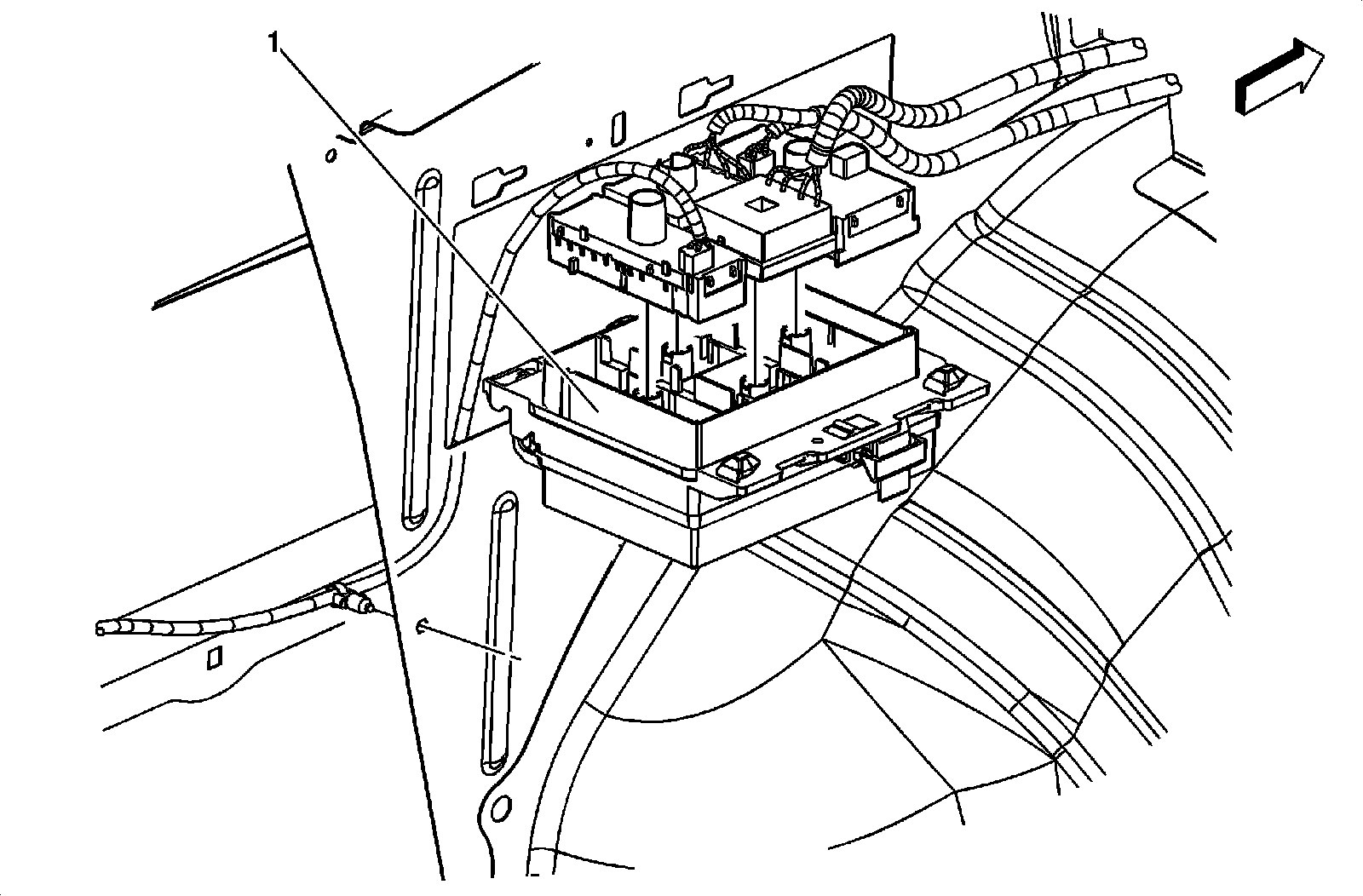
1 - Fuse Block - Rear
Factory Service Tools
Use the Manual With the Right Hardware
Pair factory procedures with proven DIY tools so the instructions are easier to execute.
Disclosure: Verified tool recommendations may earn an affiliate commission at no cost to you.
When to See a Mechanic
Stop DIY work and contact a certified mechanic immediately if any of the following apply:
- • You smell fuel, burning insulation, or see smoke.
- • Brakes feel soft, pull hard to one side, or make grinding noises.
- • The engine overheats, stalls repeatedly, or misfires under load.
- • You are missing required tools, torque specs, or safe lifting equipment.
- • You are not confident in the next step or safety outcome.
Rather have a pro handle this?
A certified mobile mechanic comes to your home or office. They bring the tools, you stay comfortable. No tow truck, no waiting room, no surprises.
Comes to youSame-day available12-month warranty
Get a Free QuoteNo obligation. See pricing before you book.