
Safety Warning
DIY auto repair can cause serious injury, fire, or vehicle damage. These guides are for informational purposes only. Always follow OEM torque specs, wear PPE, and consult a certified mechanic if you are unsure. You are solely responsible for your safety.
2008 Chevrolet Impala V6-3.5LFACTORY OEM SERVICE PROCEDURE
Powertrain Component Views
Powertrain Component Views
Left Front of the Engine Compartment
LF of the Engine Compartment:
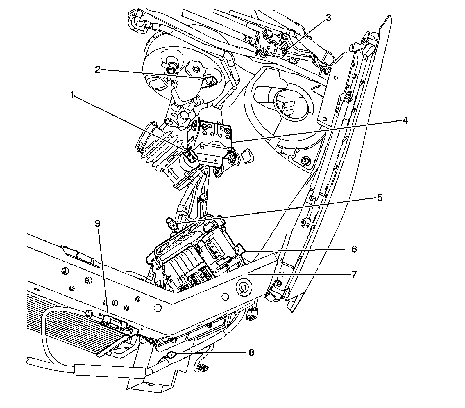
1 - Mass Air Flow (MAF) Sensor/Intake Air Temperature (IAT) Sensor
2 - Brake Booster Vacuum Sensor (LZG/LS4)
3 - Windshield Wiper Motor
4 - Electronic Brake Control Module (EBCM)
5 - A/C Refrigerant Pressure Sensor
6 - Transmission Control Module (TCM)
7 - Engine Control Module (ECM)
8 - G101
9 - Inflatable Restraint Front End Sensor - Left
Near the Air Cleaner Duct (LZE/LZ4/LZG)
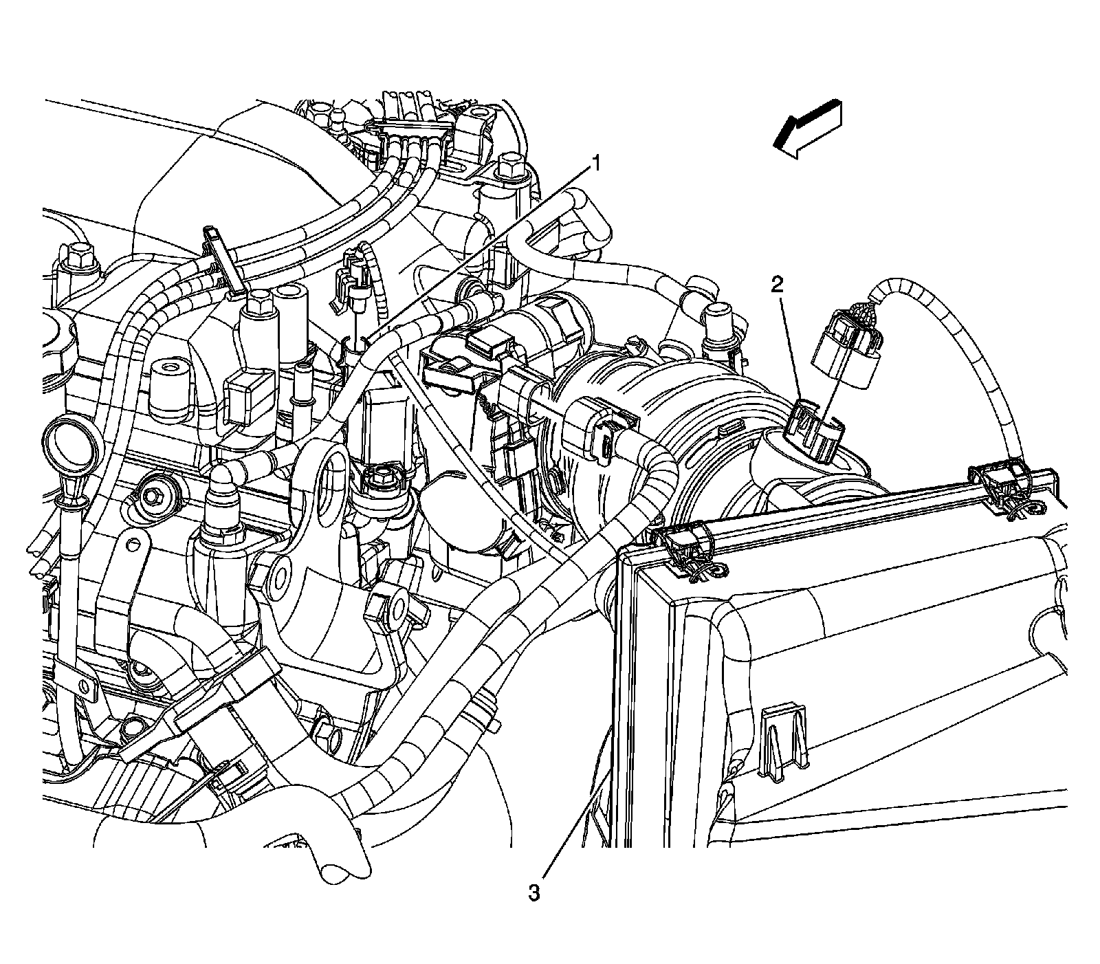
1 - Evaporative Emission (EVAP) Canister Purge Solenoid Valve
2 - Mass Air Flow (MAF) Sensor/Intake Air Temperature (IAT) Sensor
3 - Air Cleaner Housing
Left Top Side of Engine
Left Top Side Of Engine:
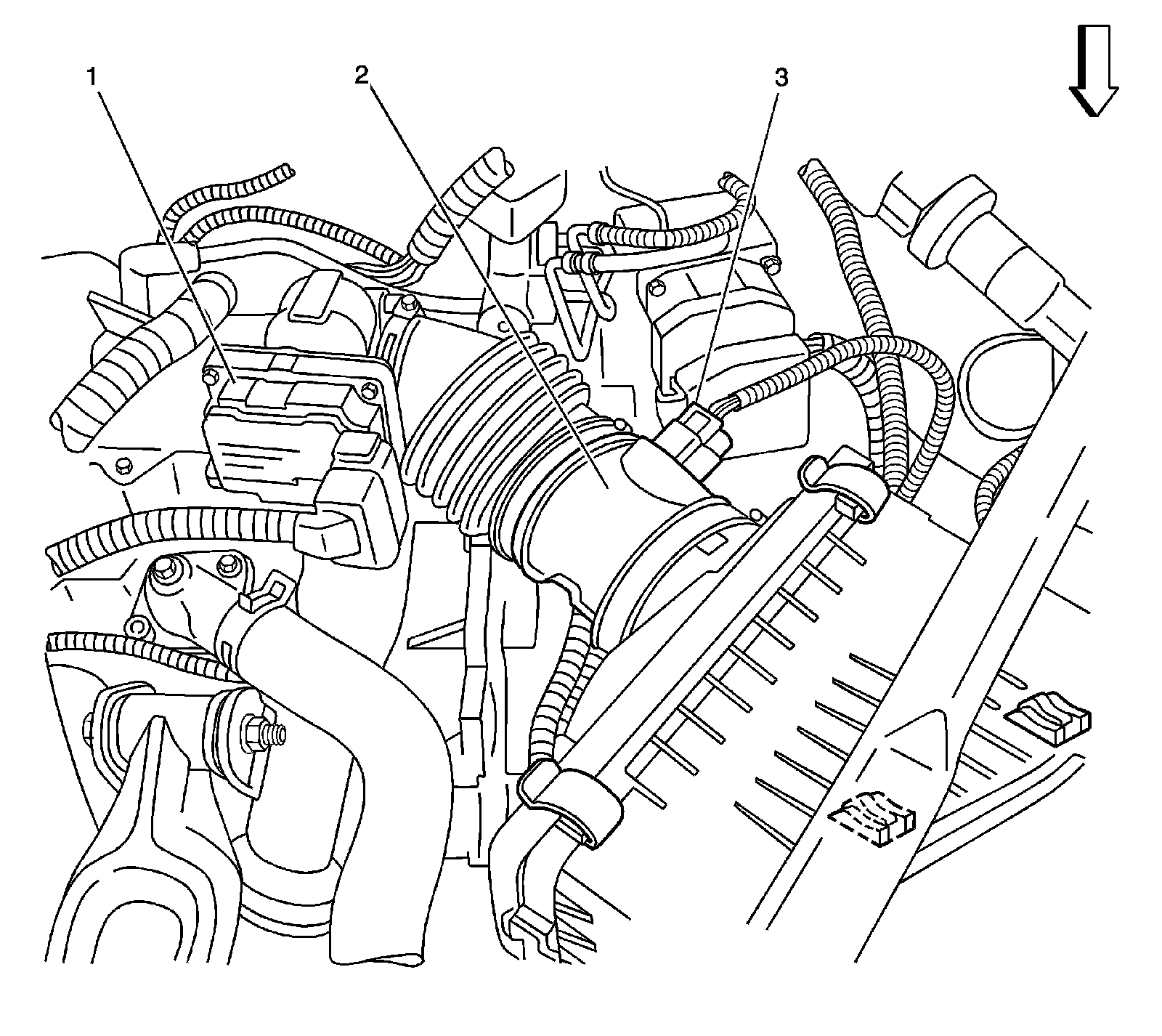
1 - Throttle Body
2 - Mass Air Flow (MAF) Sensor/Intake Air Temperature (IAT) Sensor
3 - Mass Air Flow (MAF) Sensor/Intake Air Temperature (IAT) Sensor Connector
Factory Service Tools
Use the Manual With the Right Hardware
Pair factory procedures with proven DIY tools so the instructions are easier to execute.
Disclosure: Verified tool recommendations may earn an affiliate commission at no cost to you.
When to See a Mechanic
Stop DIY work and contact a certified mechanic immediately if any of the following apply:
- • You smell fuel, burning insulation, or see smoke.
- • Brakes feel soft, pull hard to one side, or make grinding noises.
- • The engine overheats, stalls repeatedly, or misfires under load.
- • You are missing required tools, torque specs, or safe lifting equipment.
- • You are not confident in the next step or safety outcome.