
Safety Warning
DIY auto repair can cause serious injury, fire, or vehicle damage. These guides are for informational purposes only. Always follow OEM torque specs, wear PPE, and consult a certified mechanic if you are unsure. You are solely responsible for your safety.
2007 Chevrolet Uplander V6-3.9LFACTORY OEM SERVICE PROCEDURE
Control Module HVAC: Locations
HVAC Component Views
Middle Left Side of I/P Components
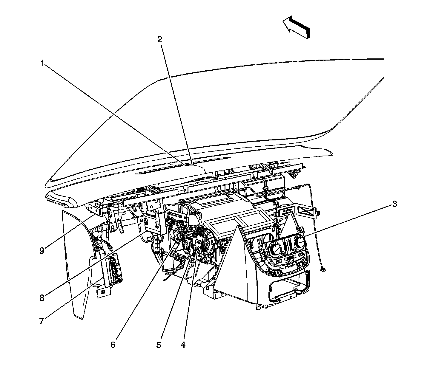
1 - Theft Light Emitted Diode (LED) (UA6)
2 - Ambient Light Sensor
3 - HVAC Control Module
4 - Vent and Floor Actuator
5 - Air Temperature Actuator (C60) or Air Temperature Actuator - Left (CJ3)
6 - Defrost Actuator
7 - Body Control Module (BCM)
8 - Digital Radio Receiver (U2K)
9 - Vehicle Communication Unit (VCU) (UE1)
Left Rear Cargo - Body Harness
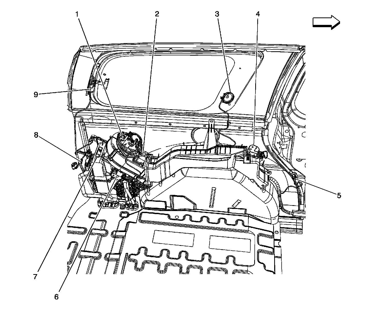
1 - Blower Motor - Auxiliary (C69)
2 - Blower Motor Control Module - Auxiliary (C69)
3 - Speaker - Rear Tweeter - Left
4 - Mode Actuator - Auxiliary (C69)
5 - Sliding Door Jamb Switch - Left (E59)
6 - Air Temperature Actuator - Auxiliary (C69)
7 - Auxiliary Power Outlet - Rear
8 - G401
9 - Rear Quarter Window Actuator - Left (A20)
Factory Service Tools
Use the Manual With the Right Hardware
Pair factory procedures with proven DIY tools so the instructions are easier to execute.
Disclosure: Verified tool recommendations may earn an affiliate commission at no cost to you.
When to See a Mechanic
Stop DIY work and contact a certified mechanic immediately if any of the following apply:
- • You smell fuel, burning insulation, or see smoke.
- • Brakes feel soft, pull hard to one side, or make grinding noises.
- • The engine overheats, stalls repeatedly, or misfires under load.
- • You are missing required tools, torque specs, or safe lifting equipment.
- • You are not confident in the next step or safety outcome.
Rather have a pro handle this?
A certified mobile mechanic comes to your home or office. They bring the tools, you stay comfortable. No tow truck, no waiting room, no surprises.
Comes to youSame-day available12-month warranty
Get a Free QuoteNo obligation. See pricing before you book.