
Safety Warning
DIY auto repair can cause serious injury, fire, or vehicle damage. These guides are for informational purposes only. Always follow OEM torque specs, wear PPE, and consult a certified mechanic if you are unsure. You are solely responsible for your safety.
2003 Chevrolet SSR V8-5.3L VIN PFACTORY OEM SERVICE PROCEDURE
Front Wheel Alignment
Front Caster and Camber Adjustment
The caster and camber adjustments are made by loosening the lower control arm adjustment bolts and repositioning the lower control arm.
Important: Before adjusting the caster and camber angles, jounce the front bumper 3 times to allow the vehicle to return to normal height.
Measure and adjust the caster and the camber with the vehicle at curb height. The front suspension Z dimension and the rear suspension D dimension are indicated in Trim Heights.
1. For an accurate reading, do not push or pull on the tires during the alignment process.
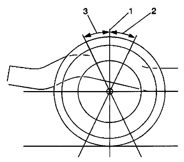
2. Determine the caster (2, 3) angle.
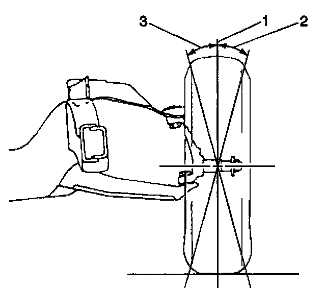
3. Determine the camber (2, 3) angle.
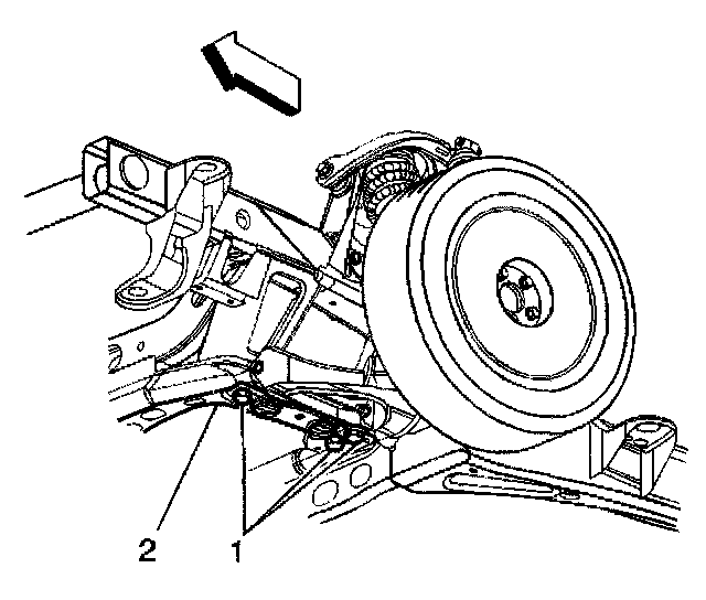
4. Loosen the lower control arm adjustment bolts (1).
Notice: Refer to Fastener Notice in Service Precautions.
5. Adjust the caster and the camber angle by repositioning the lower control arm (2) until the specifications have been met.
When the adjustments are complete, hold the lower control arm in position so that the specifications do not change while tightening the lower control arm adjustment bolts.
5.1. Tighten the front lower control arm bracket mounting bolts to 260 Nm (192 ft. lbs.).
5.2. Tighten the rear lower control arm bracket mounting bolts to 240 Nm (177 ft. lbs.).
6. Verify that the caster and the camber are still within specifications.
7. When the caster and camber are within specifications, adjust the toe.
Front Toe Adjustment
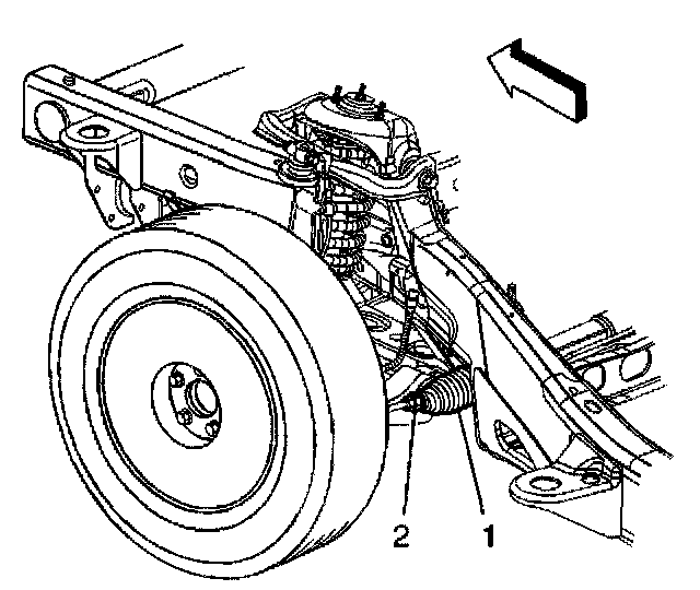
1. Loosen the jam nut on the outer tie rod (2).
Notice: Care must be taken that the boots are not twisted when rotating the inner tie rods, or damage to the boots may result.
2. Rotate the inner tie rod (1) to the required toe specification setting.
Notice: Refer to Fastener Notice in Service Precautions.
3. Tighten the jam nut on the outer tie rod.
Tighten the outer tie rod jam nut to 75 Nm (55 ft. lbs.).
4. Check the toe setting after tightening.
5. Re-adjust the toe setting if necessary.
The caster and camber adjustments are made by loosening the lower control arm adjustment bolts and repositioning the lower control arm.
Important: Before adjusting the caster and camber angles, jounce the front bumper 3 times to allow the vehicle to return to normal height.
Measure and adjust the caster and the camber with the vehicle at curb height. The front suspension Z dimension and the rear suspension D dimension are indicated in Trim Heights.
1. For an accurate reading, do not push or pull on the tires during the alignment process.
2. Determine the caster (2, 3) angle.
3. Determine the camber (2, 3) angle.
4. Loosen the lower control arm adjustment bolts (1).
Notice: Refer to Fastener Notice in Service Precautions.
5. Adjust the caster and the camber angle by repositioning the lower control arm (2) until the specifications have been met.
When the adjustments are complete, hold the lower control arm in position so that the specifications do not change while tightening the lower control arm adjustment bolts.
5.1. Tighten the front lower control arm bracket mounting bolts to 260 Nm (192 ft. lbs.).
5.2. Tighten the rear lower control arm bracket mounting bolts to 240 Nm (177 ft. lbs.).
6. Verify that the caster and the camber are still within specifications.
7. When the caster and camber are within specifications, adjust the toe.
Front Toe Adjustment
1. Loosen the jam nut on the outer tie rod (2).
Notice: Care must be taken that the boots are not twisted when rotating the inner tie rods, or damage to the boots may result.
2. Rotate the inner tie rod (1) to the required toe specification setting.
Notice: Refer to Fastener Notice in Service Precautions.
3. Tighten the jam nut on the outer tie rod.
Tighten the outer tie rod jam nut to 75 Nm (55 ft. lbs.).
4. Check the toe setting after tightening.
5. Re-adjust the toe setting if necessary.
Factory Service Tools
Use the Manual With the Right Hardware
Pair factory procedures with proven DIY tools so the instructions are easier to execute.
Disclosure: Verified tool recommendations may earn an affiliate commission at no cost to you.
When to See a Mechanic
Stop DIY work and contact a certified mechanic immediately if any of the following apply:
- • You smell fuel, burning insulation, or see smoke.
- • Brakes feel soft, pull hard to one side, or make grinding noises.
- • The engine overheats, stalls repeatedly, or misfires under load.
- • You are missing required tools, torque specs, or safe lifting equipment.
- • You are not confident in the next step or safety outcome.
Rather have a pro handle this?
A certified mobile mechanic comes to your home or office. They bring the tools, you stay comfortable. No tow truck, no waiting room, no surprises.
Comes to youSame-day available12-month warranty
Get a Free QuoteNo obligation. See pricing before you book.