
Safety Warning
DIY auto repair can cause serious injury, fire, or vehicle damage. These guides are for informational purposes only. Always follow OEM torque specs, wear PPE, and consult a certified mechanic if you are unsure. You are solely responsible for your safety.
2000 Chevrolet Express 3/4 Ton Van V8-305 5.0L VIN M SFIFACTORY OEM SERVICE PROCEDURE
VCM Replacement/Programming
NOTE: In order to prevent possible Electrostatic Discharge (ESD) damage to the VCM, do not touch the connector pins or soldered components on the circuit board.
IMPORTANT:
^ Service of the Vehicle Control Module (VCM) consists of either replacement of the VCM or reprogramming of the VCM.
^ If the VCM is being replaced, the Knock Sensor (KS) module must be transferred to the replacement VCM.
^ The replacement VCM must be programmed before the vehicle will run.
^ The replacement VCM must have the Passlock Reprogramming procedure performed before the vehicle will run.
^ The replacement VCM must have the CKP System Variation Learn procedure performed or a DTC P1336 will set.
A shorted solenoid, relay coil, or harness will not damage the output driver module (ODM) in the VCM. A shorted solenoid, relay coil, or harness will cause the circuit and the controlled component to be inoperative.
When the circuit fault is not present or the technician has repaired the fault, the output driver module (ODM) will again operate in a normal manner due to its fault protected design.
Removal Procedure
CAUTION: Refer to Battery Disconnect Caution in Service Precautions.
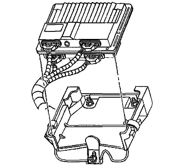
1. Disconnect the negative battery cable.
NOTE: Refer to Electrostatic Damage and the VCM Notice in Service Precautions.
2. Remove the spring retainer off the edge of the VCM.
3. Slide the VCM out of the bracket at an angle.
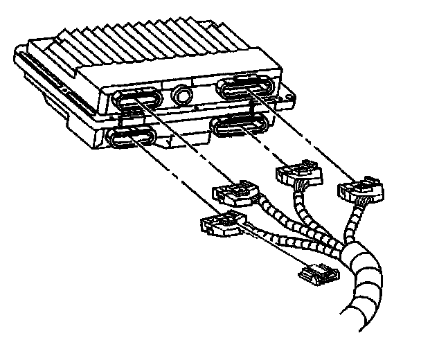
4. Remove the VCM harness connectors.
IMPORTANT: The remaining steps are only necessary for a VCM replacement.
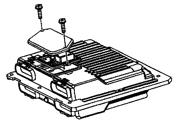
5. Remove the access cover screws.
6. Remove the VCM access cover.
IMPORTANT: Since the knock sensor module will be used in the replacement VCM, place the module in an area where the module will not be damaged.
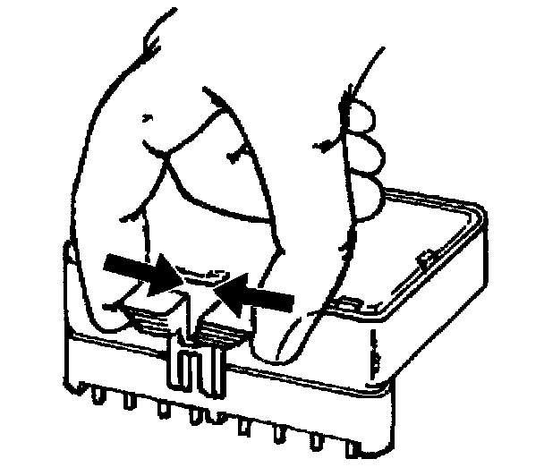
7. Gently pinch the retaining clip.
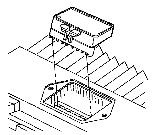
8. Pull upward to remove the knock sensor module.
Installation Procedure
IMPORTANT: Ensure that the VCM being installed is the original VCM, or that the replacement VCM service number is identical to the original VCM service number.
Steps 1-4 are only necessary for a new VCM installation:
1. Align the notches of the knock sensor module with the notches in the knock sensor module socket.
IMPORTANT: Press only on the ends of the knock sensor module. Gently press on the knock sensor module until the module is firmly seated in the socket. Listen for the click.
2. Install the knock sensor module in the knock sensor module socket.
3. Install the access cover on the VCM.
NOTE: Refer to Fastener Notice in Service Precautions.
4. Install the access cover screws.
Tighten
Tighten the screws to 4.8 N.m (42 lb in).
5. Connect the VCM harness connectors.
6. Insert the VCM into the VCM bracket.
7. Install the retaining spring over the edge of the VCM.
8. Connect the negative battery cable.
9. Program the new VCM. Programming and Relearning
IMPORTANT:
^ Service of the Vehicle Control Module (VCM) consists of either replacement of the VCM or reprogramming of the VCM.
^ If the VCM is being replaced, the Knock Sensor (KS) module must be transferred to the replacement VCM.
^ The replacement VCM must be programmed before the vehicle will run.
^ The replacement VCM must have the Passlock Reprogramming procedure performed before the vehicle will run.
^ The replacement VCM must have the CKP System Variation Learn procedure performed or a DTC P1336 will set.
A shorted solenoid, relay coil, or harness will not damage the output driver module (ODM) in the VCM. A shorted solenoid, relay coil, or harness will cause the circuit and the controlled component to be inoperative.
When the circuit fault is not present or the technician has repaired the fault, the output driver module (ODM) will again operate in a normal manner due to its fault protected design.
Removal Procedure
CAUTION: Refer to Battery Disconnect Caution in Service Precautions.
1. Disconnect the negative battery cable.
NOTE: Refer to Electrostatic Damage and the VCM Notice in Service Precautions.
2. Remove the spring retainer off the edge of the VCM.
3. Slide the VCM out of the bracket at an angle.
4. Remove the VCM harness connectors.
IMPORTANT: The remaining steps are only necessary for a VCM replacement.
5. Remove the access cover screws.
6. Remove the VCM access cover.
IMPORTANT: Since the knock sensor module will be used in the replacement VCM, place the module in an area where the module will not be damaged.
7. Gently pinch the retaining clip.
8. Pull upward to remove the knock sensor module.
Installation Procedure
IMPORTANT: Ensure that the VCM being installed is the original VCM, or that the replacement VCM service number is identical to the original VCM service number.
Steps 1-4 are only necessary for a new VCM installation:
1. Align the notches of the knock sensor module with the notches in the knock sensor module socket.
IMPORTANT: Press only on the ends of the knock sensor module. Gently press on the knock sensor module until the module is firmly seated in the socket. Listen for the click.
2. Install the knock sensor module in the knock sensor module socket.
3. Install the access cover on the VCM.
NOTE: Refer to Fastener Notice in Service Precautions.
4. Install the access cover screws.
Tighten
Tighten the screws to 4.8 N.m (42 lb in).
5. Connect the VCM harness connectors.
6. Insert the VCM into the VCM bracket.
7. Install the retaining spring over the edge of the VCM.
8. Connect the negative battery cable.
9. Program the new VCM. Programming and Relearning
Factory Service Tools
Use the Manual With the Right Hardware
Pair factory procedures with proven DIY tools so the instructions are easier to execute.
Disclosure: Verified tool recommendations may earn an affiliate commission at no cost to you.
When to See a Mechanic
Stop DIY work and contact a certified mechanic immediately if any of the following apply:
- • You smell fuel, burning insulation, or see smoke.
- • Brakes feel soft, pull hard to one side, or make grinding noises.
- • The engine overheats, stalls repeatedly, or misfires under load.
- • You are missing required tools, torque specs, or safe lifting equipment.
- • You are not confident in the next step or safety outcome.
Rather have a pro handle this?
A certified mobile mechanic comes to your home or office. They bring the tools, you stay comfortable. No tow truck, no waiting room, no surprises.
Comes to youSame-day available12-month warranty
Get a Free QuoteNo obligation. See pricing before you book.