
Safety Warning
DIY auto repair can cause serious injury, fire, or vehicle damage. These guides are for informational purposes only. Always follow OEM torque specs, wear PPE, and consult a certified mechanic if you are unsure. You are solely responsible for your safety.
1995 Chevrolet S10/T10 P/U 4WD V6-262 4.3L VIN W CPIFACTORY OEM SERVICE PROCEDURE
With Vehicle Control Module (VCM-A)
Service of the Vehicle Control Module (VCM-A) consists of replacement of VCM-A. If the diagnostics call for replacement of the VCM-A, it will be necessary to transfer the Knock Sensor (KS) Calibration Programmable Read Only Memory (PROM) and program the Electrically Erasable Programmable Read Only Memory (EEPROM) in the VCM-A using the procedure under EEPROM Programming. Testing and Inspection
NOTE: When replacing the production VCM-A with a service VCM-A (controller), it is important to transfer the broadcast code and production VCM-A number to the service VCM-A label. This will allow positive identification of VCM-A parts throughout the service life of the vehicle. Also transfer the KS Calibration PROM.
KS Calibration PROM
Refer to Knock Sensor (KS) Module for removal and installation of the KS Calibration PROM. Service and Repair
NOTE: To prevent internal VCM-A damage, the ignition must be "OFF,' when disconnecting or reconnecting power to the VCM-A (for example, battery cable, Engine Control Module (ECM) fuse, jumper cables, etc.).
CAUTION: To prevent possible Electrostatic Discharge damage to the VCM-A, Do Not touch the connector pins or soldered components on the circuit board.
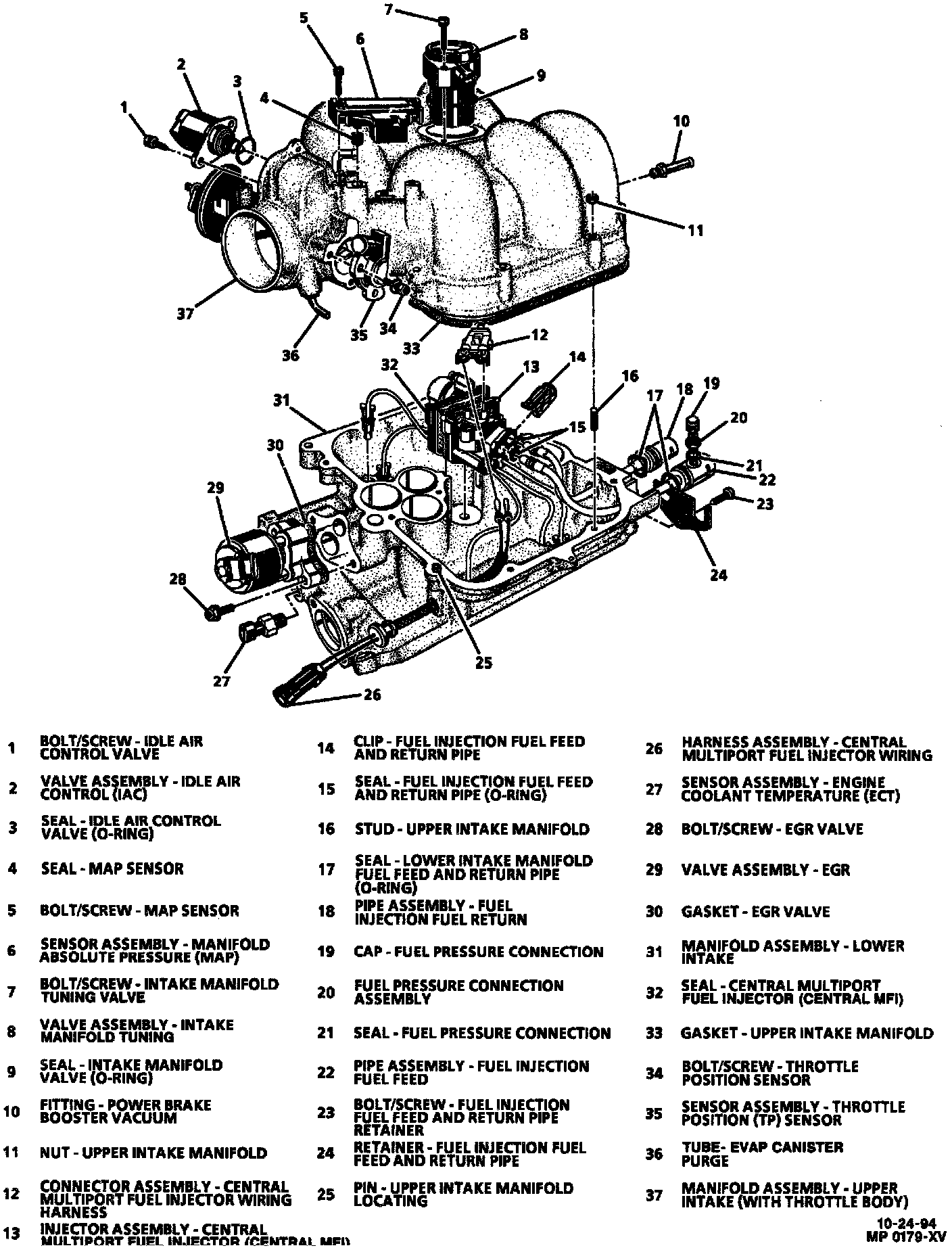
REMOVE OR DISCONNECT
1. Negative battery cable.
2. Plastic cover.
3. Wire harnesses, including:
^ Throttle Position (TP) sensor.
^ Idle Air Control (IAC) motor.
^ Manifold Absolute Pressure (MAP) sensor.
^ Intake manifold tuning valve assembly.
4. Throttle and cruise cable from upper intake manifold.
5. Ignition coil.
6. Crankcase ventilation hose at upper intake manifold.
7. Vacuum hoses at front and rear of upper intake manifold.
8. Air cleaner snorkel.
9. Upper intake manifold bolts and studs.
^ Mark the location of all studs for proper reassembly.
10. Upper intake manifold.
NOTE: Do Not attempt to disassemble the Central MFI assembly, it is serviceable as an assembly.
CAUTION: Refer to Fuel Pressure Relief Procedure before disconnecting fuel lines. Service and Repair
REMOVE OR DISCONNECT
1. Remove injector wiring harness connector at Central MFI assembly.
2. Fuel fitting clip and discard.
3. Fuel inlet and return tube and fitting assembly.
^ Discard 0-ring seals.
4. Central MFI assembly.
^ Squeeze poppet nozzle locking tabs together while lifting nozzle out of casting socket.
^ After removing the six poppet nozzles, lift the Central MFI assembly out of casting.
INSTALL OR CONNECT
WARNING: To reduce the risk of fire and personal injury, verify that the poppet nozzles are firmly seated and locked in their casting sockets. An unlocked poppet nozzle could work loose from its socket thus resulting in a fuel leak.
1. Central MFI assembly.
^ Align Central MFI assembly grommet with the casting grommet slots and push down until it is seated in bottom guide hole.
^ Push poppet nozzles into casting sockets.
INSPECT
^ Poppet nozzles must be firmly seated and locked in casting sockets. Refer to "CAUTION" statement above.
2. Fuel inlet and return tube and fitting assembly.
^ New 0-ring seals coated with clean engine oil.
3. New fuel fitting clip.
NOTE: Test for fuel leakage. Pressurize fuel system, verify no fuel leakage at inlet and return tube to Central MFI unit.
NOTE: When replacing the production VCM-A with a service VCM-A (controller), it is important to transfer the broadcast code and production VCM-A number to the service VCM-A label. This will allow positive identification of VCM-A parts throughout the service life of the vehicle. Also transfer the KS Calibration PROM.
KS Calibration PROM
Refer to Knock Sensor (KS) Module for removal and installation of the KS Calibration PROM. Service and Repair
NOTE: To prevent internal VCM-A damage, the ignition must be "OFF,' when disconnecting or reconnecting power to the VCM-A (for example, battery cable, Engine Control Module (ECM) fuse, jumper cables, etc.).
CAUTION: To prevent possible Electrostatic Discharge damage to the VCM-A, Do Not touch the connector pins or soldered components on the circuit board.
Central MFI Assembly Parts Identification:
REMOVE OR DISCONNECT
1. Negative battery cable.
2. Plastic cover.
3. Wire harnesses, including:
^ Throttle Position (TP) sensor.
^ Idle Air Control (IAC) motor.
^ Manifold Absolute Pressure (MAP) sensor.
^ Intake manifold tuning valve assembly.
4. Throttle and cruise cable from upper intake manifold.
5. Ignition coil.
6. Crankcase ventilation hose at upper intake manifold.
7. Vacuum hoses at front and rear of upper intake manifold.
8. Air cleaner snorkel.
9. Upper intake manifold bolts and studs.
^ Mark the location of all studs for proper reassembly.
10. Upper intake manifold.
NOTE: Do Not attempt to disassemble the Central MFI assembly, it is serviceable as an assembly.
CAUTION: Refer to Fuel Pressure Relief Procedure before disconnecting fuel lines. Service and Repair
REMOVE OR DISCONNECT
1. Remove injector wiring harness connector at Central MFI assembly.
2. Fuel fitting clip and discard.
3. Fuel inlet and return tube and fitting assembly.
^ Discard 0-ring seals.
4. Central MFI assembly.
^ Squeeze poppet nozzle locking tabs together while lifting nozzle out of casting socket.
^ After removing the six poppet nozzles, lift the Central MFI assembly out of casting.
INSTALL OR CONNECT
WARNING: To reduce the risk of fire and personal injury, verify that the poppet nozzles are firmly seated and locked in their casting sockets. An unlocked poppet nozzle could work loose from its socket thus resulting in a fuel leak.
1. Central MFI assembly.
^ Align Central MFI assembly grommet with the casting grommet slots and push down until it is seated in bottom guide hole.
^ Push poppet nozzles into casting sockets.
INSPECT
^ Poppet nozzles must be firmly seated and locked in casting sockets. Refer to "CAUTION" statement above.
2. Fuel inlet and return tube and fitting assembly.
^ New 0-ring seals coated with clean engine oil.
3. New fuel fitting clip.
NOTE: Test for fuel leakage. Pressurize fuel system, verify no fuel leakage at inlet and return tube to Central MFI unit.
Factory Service Tools
Use the Manual With the Right Hardware
Pair factory procedures with proven DIY tools so the instructions are easier to execute.
Disclosure: Verified tool recommendations may earn an affiliate commission at no cost to you.
When to See a Mechanic
Stop DIY work and contact a certified mechanic immediately if any of the following apply:
- • You smell fuel, burning insulation, or see smoke.
- • Brakes feel soft, pull hard to one side, or make grinding noises.
- • The engine overheats, stalls repeatedly, or misfires under load.
- • You are missing required tools, torque specs, or safe lifting equipment.
- • You are not confident in the next step or safety outcome.
Rather have a pro handle this?
A certified mobile mechanic comes to your home or office. They bring the tools, you stay comfortable. No tow truck, no waiting room, no surprises.
Comes to youSame-day available12-month warranty
Get a Free QuoteNo obligation. See pricing before you book.