
Safety Warning
DIY auto repair can cause serious injury, fire, or vehicle damage. These guides are for informational purposes only. Always follow OEM torque specs, wear PPE, and consult a certified mechanic if you are unsure. You are solely responsible for your safety.
2012 Acura MDX V6-3.7LFACTORY OEM SERVICE PROCEDURE
Keyless/Power Door Locks/Security System (MICUs, Relay Control Module, MPCS Units) Input Test
Keyless/Power Door Locks/Security System (MICU, Rear MICU, Relay Control Module, and Driver's and Passenger's MPCS Unit) Input Test
NOTE: Before testing, troubleshoot the multiplex integrated control unit first, using B-CAN system Diagnosis Test Mode A Troubleshooting - B-CAN System Diagnosis Test Mode A.
MICU
1. Turn the ignition switch to LOCK (0).
2. Remove the left kick panel Service and Repair.
3. Disconnect under-dash fuse/relay box connectors E, F, H, K, N, Q, and P.
NOTE: All connector views are wire side of female terminals.
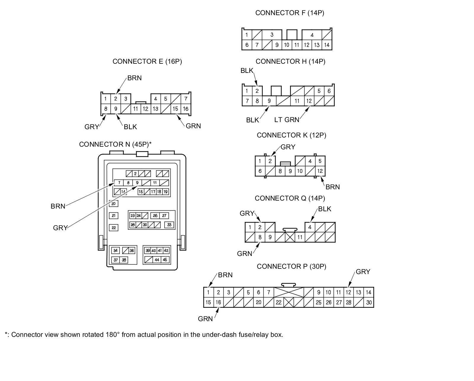
4. Inspect the connector and socket terminals to be sure they are all making good contact.
- If the terminals are bent, loose, or corroded, repair them as necessary, and recheck the system.
- If the terminals look OK, go to step 5.
5. With the connectors still disconnected, do the following input tests:
- If any test indicates a problem, find and correct the cause, then recheck the system.
- If all the input tests prove OK, go to step 6.

6. Reconnect the remaining connectors, then turn the ignition switch to ON (II), and do the following input tests:
- If any test indicates a problem, find and correct the cause, then recheck the system.
- If all the input tests prove OK, go to step 7.
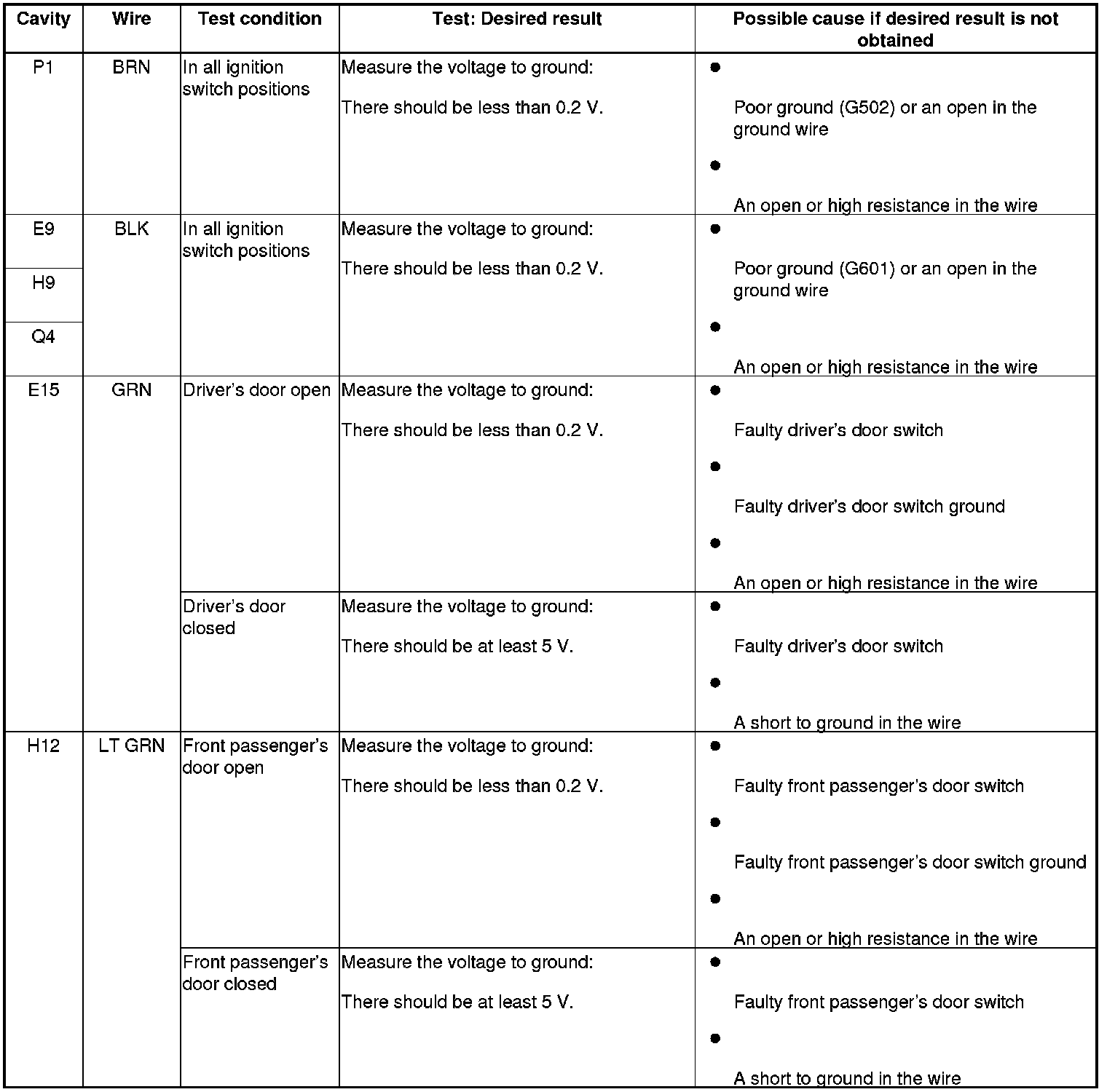
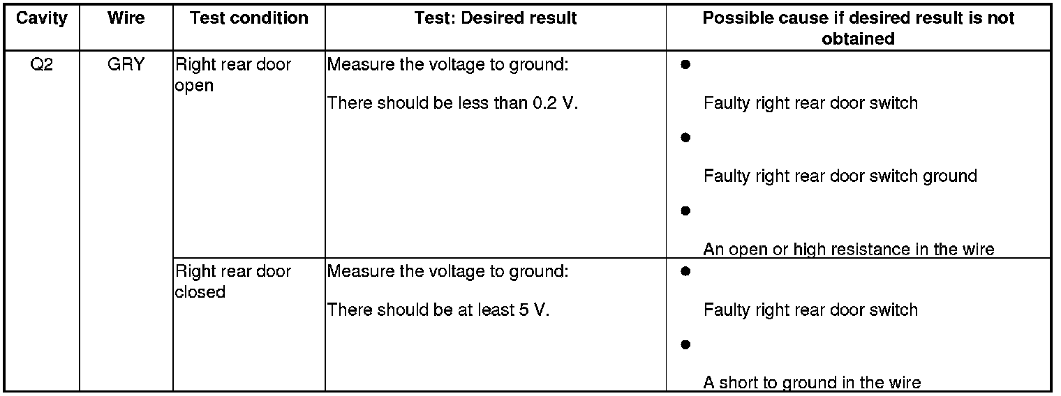
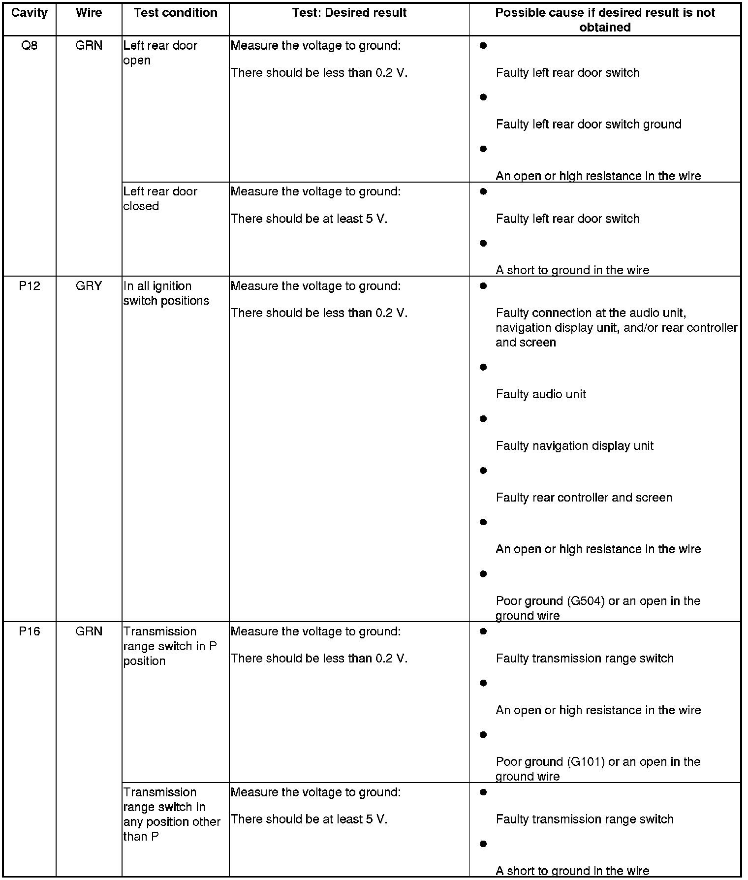

Rear Fuse/Relay Box
7. Turn the ignition switch to LOCK (0).
8. Remove the left rear side trim Interior Trim Removal/Installation - Rear Side Area.
9. Disconnect rear fuse/relay box connectors B (34P) and C (42P).
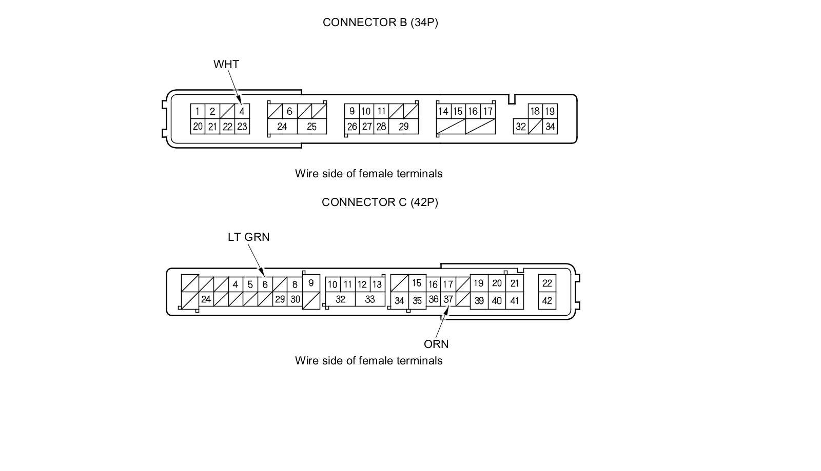
10. Inspect the connector and socket terminals to be sure they are all making good contact.
- If the terminals are bent, loose, or corroded, repair them as necessary, and recheck the system.
- If the terminals look OK, go to step 11.
11. With the connectors still disconnected, do the following input tests:
- If any test indicates a problem, find and correct the cause, then recheck the system.
- If all the input tests prove OK, go to step 12.
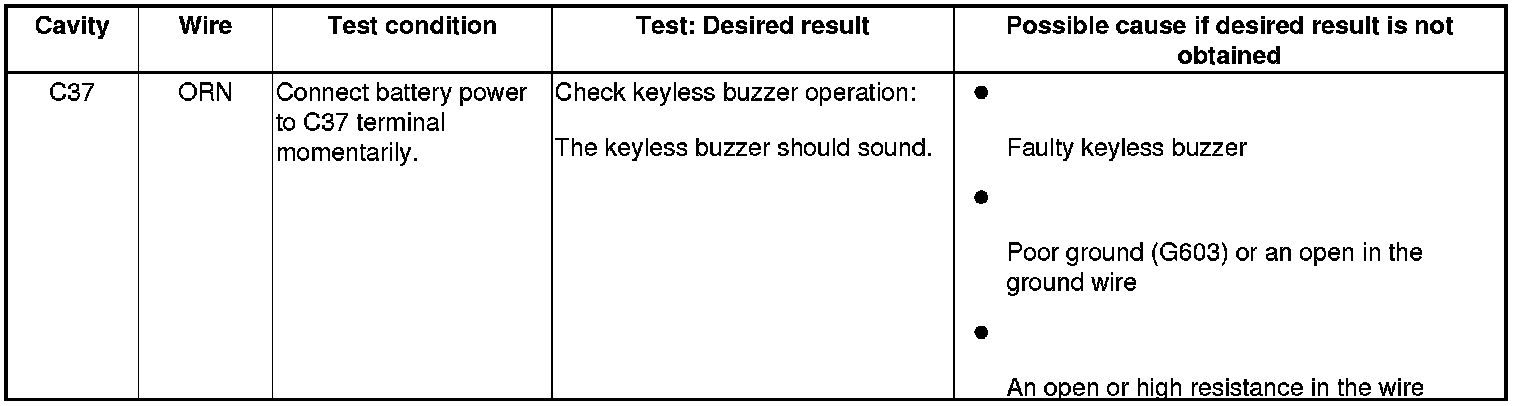
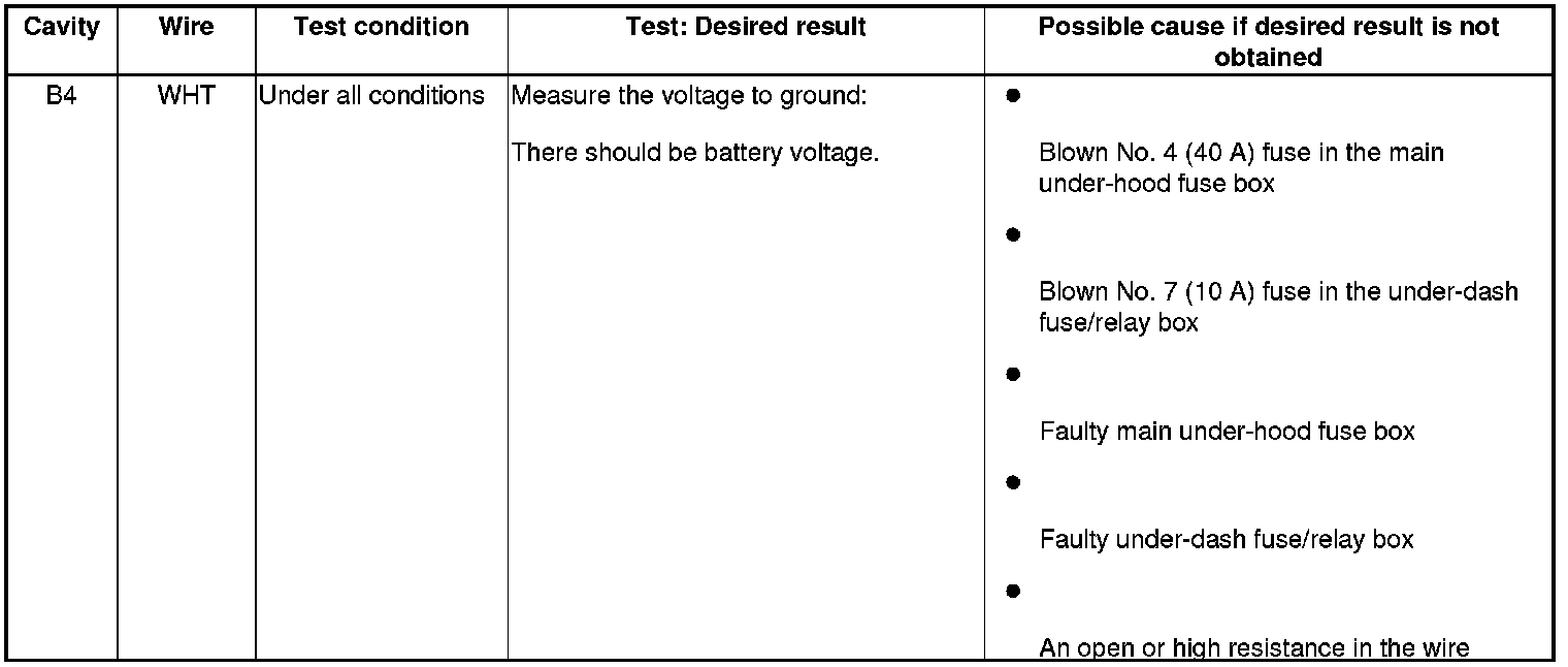
12. Reconnect the connectors, then turn the ignition switch to ON (II), and do the following input tests:
- If any test indicates a problem, find and correct the cause, then recheck the system.
- If all the input tests prove OK, go to step 13.
Relay Control Module
13. Turn the ignition switch to LOCK (0).
14. Remove the under-hood fuse/relay box Under-Hood Fuse/Relay Box Removal and Installation.
15. Disconnect under-hood fuse/relay box (relay control module part) connector D (10P) and H (9P).

16. Inspect the connector and socket terminals to be sure they are all making good contact.
- If the terminals are bent, loose, or corroded, repair them as necessary, and recheck the system.
- If the terminals look OK, go to step 17.
17. With the connectors still disconnected, do the following input tests:
- If any test indicates a problem, find and correct the cause, then recheck the system.
- If all the input tests prove OK, go to step 18.

18. Reconnect the connectors, then turn the ignition switch to ON (II), and do the following input tests.
- If any test indicates a problem, find and correct the cause, then recheck the system.
- If all the input tests prove OK, go to step 19.

Driver's MPCS Unit
19. Turn the ignition switch to LOCK (0).
20. Remove the driver's door panel Front Door Panel Removal/Installation.
21. Disconnect driver's MPCS unit connectors A (40P) and B (14P).

22. Inspect the connector and socket terminals to be sure they are all making good contact.
- If the terminals are bent, loose, or corroded, repair them as necessary, and recheck the system.
- If the terminals look OK, go to step 23.
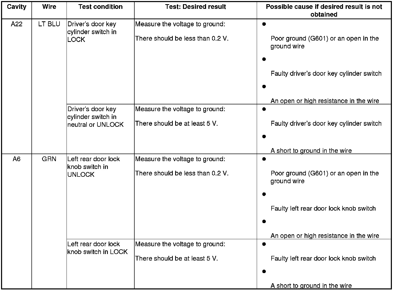
23. With the connectors still disconnected, do the following input tests:
- If any test indicates a problem, find and correct the cause, then recheck the system.
- If all the input tests prove OK, go to step 24.
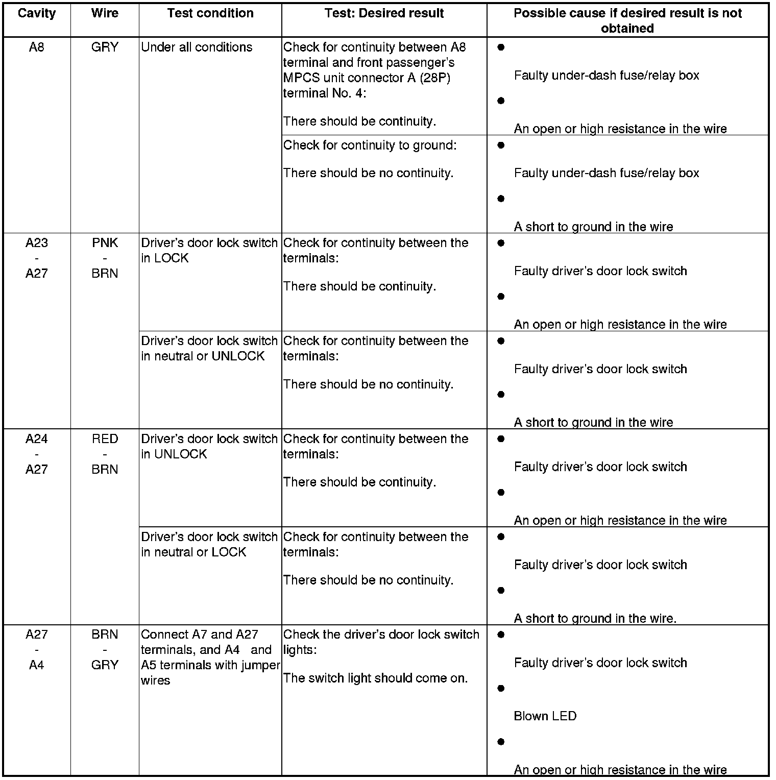
24. Reconnect the connectors, then turn the ignition switch to ON (II), and do the following input tests:
- If any test indicates a problem, find and correct the cause, then recheck the system.
- If all the input tests prove OK, go to step 25.


Front Passenger's MPCS Unit
25. Turn the ignition switch to LOCK (0).
26. Remove the front passenger's door panel Front Door Panel Removal/Installation.
27. Disconnect front passenger's MPCS unit connectors A (28P) and B (14P).
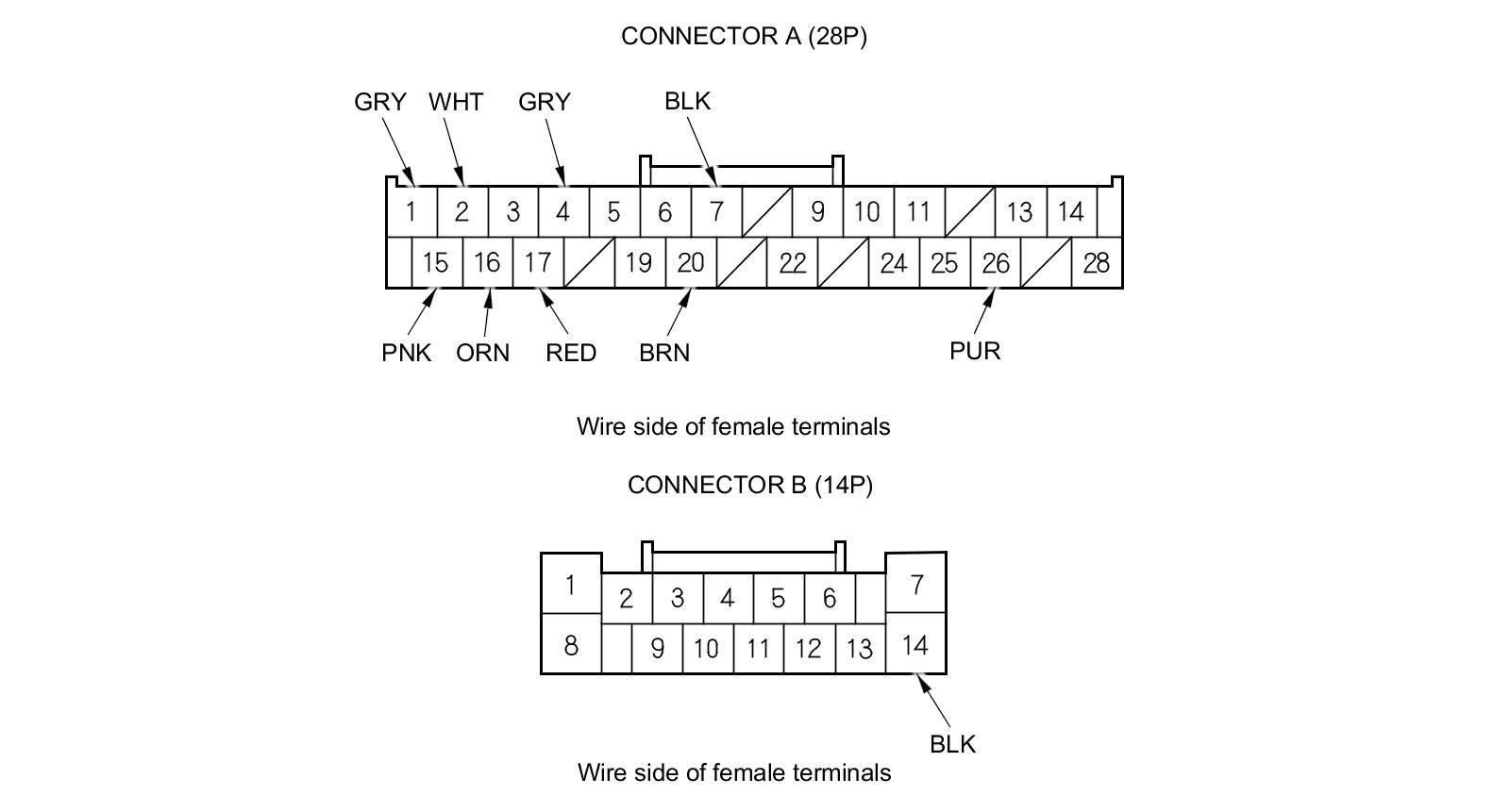
28. Inspect the connector and socket terminals to be sure they are all making good contact.
- If the terminals are bent, loose, or corroded, repair them as necessary, and recheck the system.
- If the terminals look OK, go to step 29.
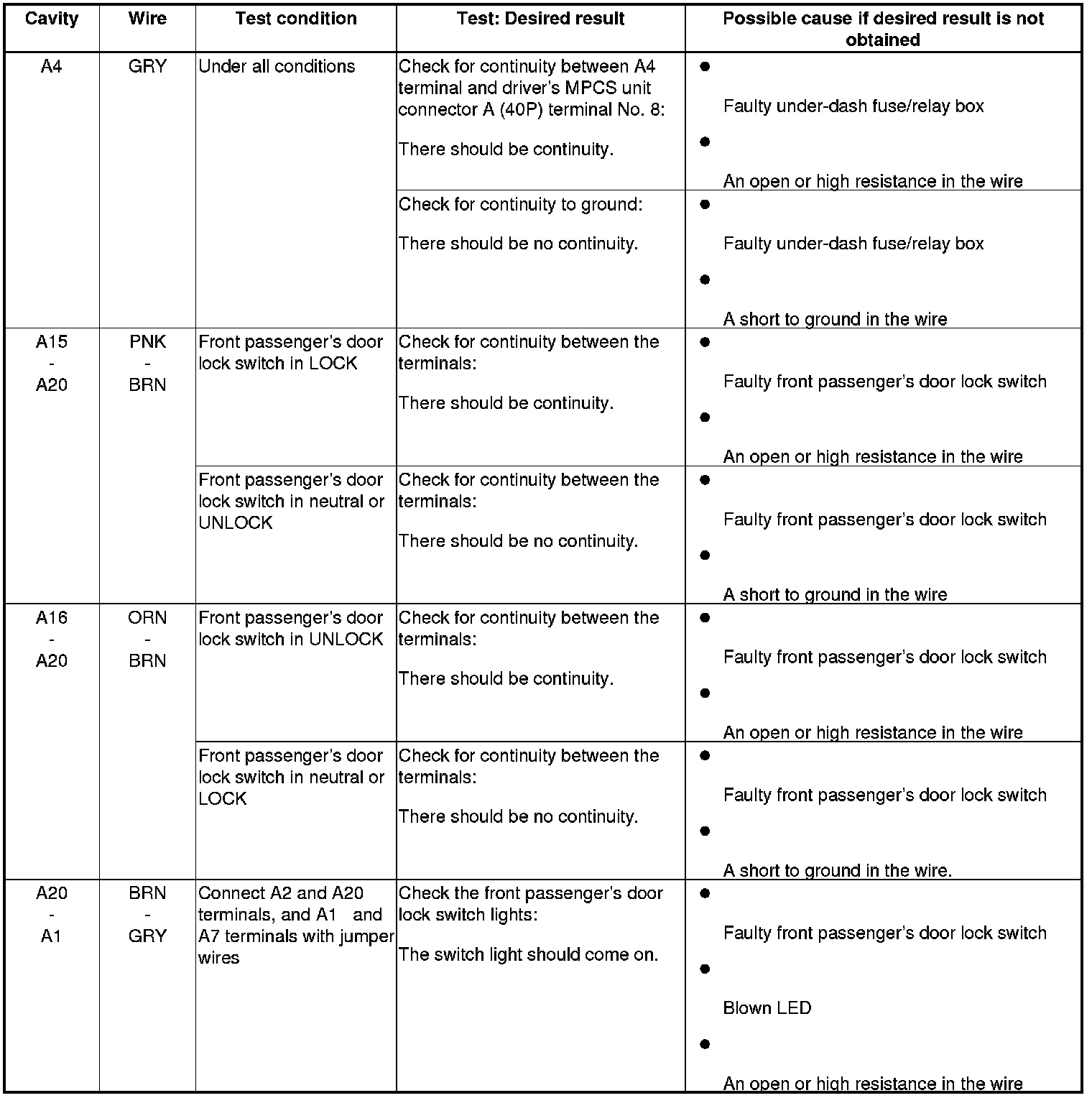
29. With the connectors still disconnected, do the following input tests:
- If any test indicates a problem, find and correct the cause, then recheck the system.
- If all the input tests prove OK, go to step 30.
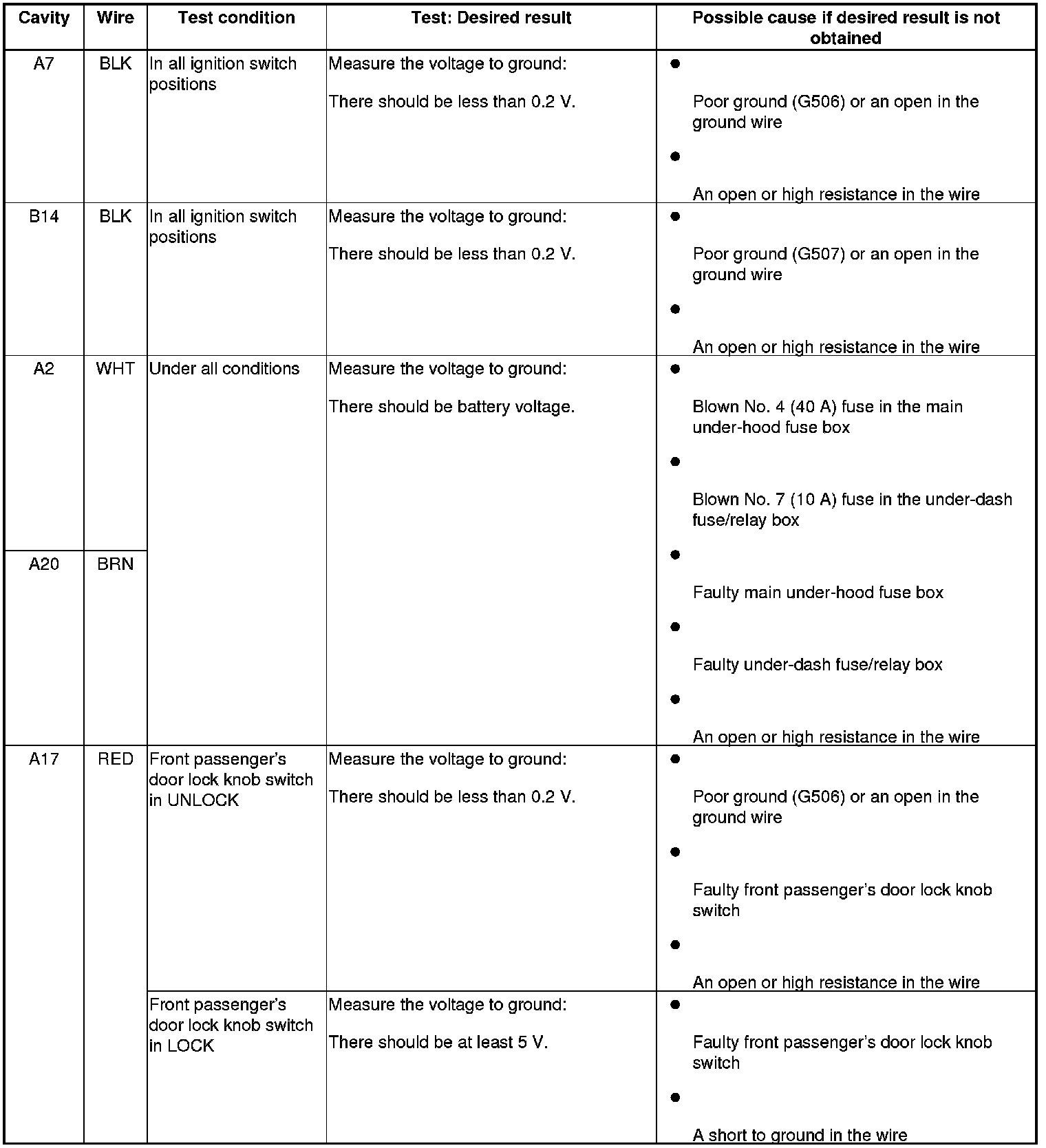
30. Reconnect the connectors, then turn the ignition switch to ON (II), and do the following input tests:
- If any test indicates a problem, find and correct the cause, then recheck the system.
- If all the input tests prove OK, go to step 31.

31. If multiple failures are found on more than one control unit, replace the under-dash fuse/relay box (includes the MICU) Under-Dash Fuse/Relay Box Removal and Installation. If input failures are related to a particular control unit, replace the control unit.
Factory Service Tools
Use the Manual With the Right Hardware
Pair factory procedures with proven DIY tools so the instructions are easier to execute.
Disclosure: Verified tool recommendations may earn an affiliate commission at no cost to you.
When to See a Mechanic
Stop DIY work and contact a certified mechanic immediately if any of the following apply:
- • You smell fuel, burning insulation, or see smoke.
- • Brakes feel soft, pull hard to one side, or make grinding noises.
- • The engine overheats, stalls repeatedly, or misfires under load.
- • You are missing required tools, torque specs, or safe lifting equipment.
- • You are not confident in the next step or safety outcome.